Heat pump air conditioner and control method thereof
A heat pump air conditioner and control method technology, applied in heating and cooling combinations, refrigerators, refrigeration components, etc., can solve problems such as reduced comfort and reduced system energy efficiency, and achieve the effect of ensuring comfort
- Summary
- Abstract
- Description
- Claims
- Application Information
AI Technical Summary
Problems solved by technology
Method used
Image
Examples
Embodiment 1
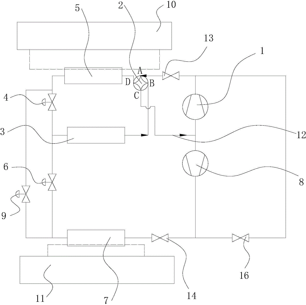
[0033] This preferred embodiment provides a heat pump air conditioner. Such as figure 1 As shown, the heat pump air conditioner includes a first compressor 1, a second compressor 8, a first heat exchanger 3, a fan convection heat exchange terminal device 10, a second heat exchanger 5, a radiation terminal device 11, and a third heat exchanger Device 7, and four-way valve 2.
[0034] The A end of the four-way valve 2 is connected to the outlet port of the first compressor 1, the B end is connected to the first end of the first heat exchanger 3, and the C end is respectively connected to the first compressor 1 and the first compressor 1 through the suction pipe 12. The inlet end and the D end of the second compressor 8 are connected to the first end of the second heat exchanger 5 .
[0035] The second end of the second heat exchanger 5 communicates with the second end of the first heat exchanger 3 ; the second heat exchanger 5 exchanges heat with the fan convective heat exchan...
Embodiment 2
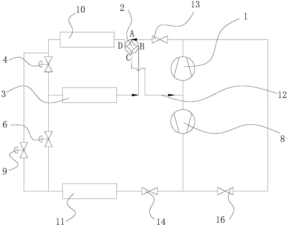
[0050] This preferred embodiment provides a heat pump air conditioner. Such as figure 2 As shown, the heat pump air conditioner includes a first compressor 1 , a second compressor 8 , a first heat exchanger 3 , a fan convection heat exchange terminal device 10 , a radiation terminal device 11 , and a four-way valve 2 .
[0051] The first end of the fan convection heat exchange end device 10 is connected to the D end of the four-way valve 2, and the second end is connected to the second end of the first heat exchanger 3; the first end of the radiation end device 11 is connected to the second compressor The outlet end of the machine 8, and the second end communicates with the second end of the first heat exchanger 3. At this time, the refrigerant directly flows through the fan convection heat exchange end device 10 and the radiation end device 11 to exchange heat.
[0052] A first expansion valve 4 is provided between the second end of the fan convection heat exchange termina...
Embodiment 3
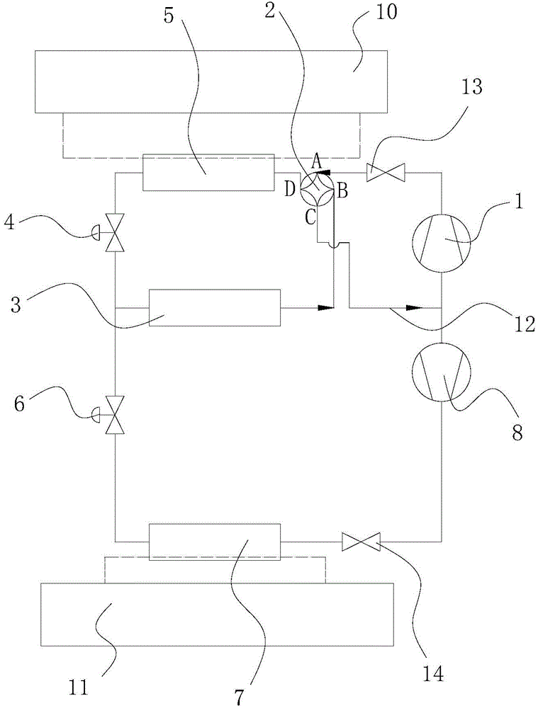
[0056] This preferred embodiment provides a heat pump air conditioner, the structure of which is basically the same as that of the first preferred embodiment. Such as image 3 As shown, the heat pump air conditioner includes a first compressor 1, a second compressor 8, a first heat exchanger 3, a fan convection heat exchange terminal device 10, a second heat exchanger 5, a radiation terminal device 11, and a third heat exchanger Device 7, and four-way valve 2. The inlet ends of the first compressor 1 and the second compressor 8 are respectively connected to the C end of the four-way valve 2 . The first end of the second heat exchanger 5 is connected to the D end of the four-way valve 2, and the second end is connected to the second end of the first heat exchanger 3; the first end of the third heat exchanger 7 is connected to the second The outlet end of the compressor 8 , the second end communicates with the second end of the first heat exchanger 3 .
[0057] The difference...
PUM
 Abstract
Description
Claims
Application Information
 - R&D
- Intellectual Property
- Life Sciences
- Materials
- Tech Scout
- Unparalleled Data Quality
- Higher Quality Content
- 60% Fewer Hallucinations
Browse by: Latest US Patents, China's latest patents, Technical Efficacy Thesaurus, Application Domain, Technology Topic, Popular Technical Reports.
© 2025 PatSnap. All rights reserved.Legal|Privacy policy|Modern Slavery Act Transparency Statement|Sitemap|About US| Contact US: help@patsnap.com


