
Multi-point-location nitrogen oxide continuous monitoring device and continuous monitoring method for SCR reactors

A nitrogen oxide and monitoring device technology, applied in the field of flue gas denitrification, can solve the problems that it is difficult to accurately reflect the overall uniform distribution performance of the SCR reactor, and there is no continuous monitoring device for the SCR inlet, so as to improve the monitoring accuracy and avoid material pollution. Consumption, the effect of ensuring equipment safety

Inactive Publication Date: 2015-09-02
河北涿州京源热电有限责任公司
View PDF5 Cites 6 Cited by
  • Summary
  • Abstract
  • Description
  • Claims
  • Application Information

AI Technical Summary

Problems solved by technology

In view of this, the "Technical Guidelines for Flue Gas Denitration in Thermal Power Plants" (DL / T296-2011) requires that the SCR inlet NH 3 The deviation rate of / NOx molar ratio is ≤±10%. After installing the SCR denitrification device, the field can only rely on the grid method to manually complete the uniformity test by the test personnel, and there is no way to realize the SCR inlet NH 3 / Continuous monitoring device for NOx uniformity, while SCR inlet NH 3 The quality of / NOx uniformity has a crucial impact on the amount of ammonia slip
"Technical Guidelines for Flue Gas Denitrification in Thermal Power Plants" (DL / T296-2011) also proposed that "multi-point extraction of flue gas should be used to collect flue gas samples for analysis to improve detection reliability". According to the above description, domestic thermal power plants SCR projects are designed and arranged according to the "single set, single point, single measurement" method of online monitoring instruments at the outlet and inlet positions of the SCR reactor, which is difficult to accurately reflect the overall uniform performance of the SCR reactor

Method used


Image

  • Multi-point-location nitrogen oxide continuous monitoring device and continuous monitoring method for SCR reactors
  • Multi-point-location nitrogen oxide continuous monitoring device and continuous monitoring method for SCR reactors

Examples


Embodiment Construction

[0034]Embodiments of the present invention will be further described in detail below in conjunction with the accompanying drawings and examples. The following examples are used to illustrate the present invention, but should not be used to limit the scope of the present invention.

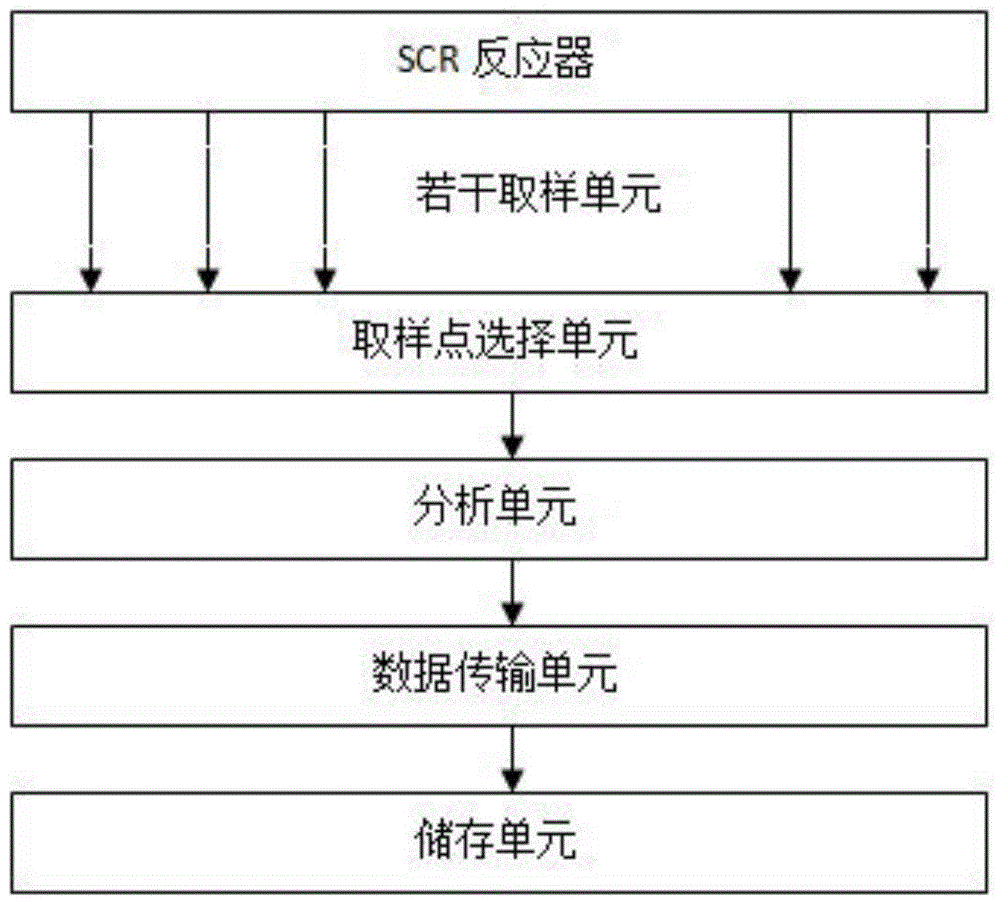
[0035] For the structure and working principle of the multi-point nitrogen oxide continuous monitoring device of the SCR system of this embodiment, please refer to figure 1 with figure 2 . The multi-point nitrogen oxide continuous monitoring device of the SCR system includes a plurality of sample continuous sampling units 2 for sampling the flue gas in the outlet flue 1 of the SCR reactor. Wherein, it is preferable to distribute the sampling points of the continuous sampling unit 2 according to the requirement and according to the arrangement principle of the grid testing method. The specific number of sampling points is determined according to different engineering needs. In actual engineering...


PUM


Abstract

The present invention relates to the technical field of flue gas denitrification and provides a multi-point-location nitrogen oxide continuous monitoring device and a continuous monitoring method for SCR reactors. According to the device, a plurality of continuous sampling units, a sampling point selection unit, an analysis unit and a data transmission unit are combined. In this way, any typical point on the cross section of the outlet of an SCR reactor can be monitored at any time according to needs. Meanwhile, multiple typical points on the cross section of the outlet of the SCR reactor can be monitored at the same time. Therefore, the NOx monitoring accuracy at the outlet of the SCR reactor is improved, and the large monitoring error of the NOx between the outlet of the SCR reactor and the main discharge port of the SCR reactor can be eliminated. Through analyzing and processing the monitoring result of the continuous monitoring device, the overall performance of the SCR system can be accurately analyzed, so that the local abnormal state of the system can be found out timely. The device provides a clear and accurate data support for the promotion of the entire SCR system and also provides an important means for monitoring and preventing the ammonia escape phenomenon. Therefore, the safety of boilers, preheaters and the like can be ensured.

Description

technical field [0001] The invention relates to the technical field of flue gas denitrification, in particular to a multi-point nitrogen oxide continuous monitoring device and method for an SCR reactor. Background technique [0002] Flue gas denitrification is currently widely used in developed countries to reduce NO x (Nitrogen oxides) emission method, the selective catalytic reduction method (Selective catalytic reduction, referred to as SCR) and the selective non-catalytic reduction method (Selective non-catalytic reduction, hereinafter referred to as SNCR) are widely used. Among them, the denitrification of SCR The rate is higher. The invention right of SCR belongs to the United States, and Japan took the lead in realizing its commercial application in the 1970s. At present, this technology has been widely used in developed countries. Among them, more than 93% of flue gas denitrification in Japan uses SCR, and there are more than 300 sets of operating devices; power p...

Claims


Application Information

Patent Timeline
IPC IPC(8): G01N33/00
Inventor 刘振生王斌李刚王兰忠刘金强
Owner 河北涿州京源热电有限责任公司
Learn More