
Object lens driving table

A technology of objective lens and motion platform, used in microscopes, optics, instruments, etc., can solve the problems of small observation accuracy, insufficient accuracy, and large volume.

Inactive Publication Date: 2015-09-02
SUZHOU UNIV
View PDF6 Cites 4 Cited by
  • Summary
  • Abstract
  • Description
  • Claims
  • Application Information

AI Technical Summary

Problems solved by technology

However, the clarity of traditional optical microscopes depends entirely on the magnification of the optical objective lens, and the maximum magnification of the current optical objective lens can only reach 1600 times (the resolution of the human eye is about 1mm, taking 1600 times magnification as an example, the minimum Observation accuracy 0.625 microns)
Obviously the traditional optical microscope can no longer meet the demand here
[0003] However, at present, the existing objective lens driving devices are generally driven by motors or manually adjusted. Such devices have disadvantages such as insufficient precision, slow response time, large volume and high noise.

Method used


Image

  • Object lens driving table
  • Object lens driving table
  • Object lens driving table

Examples


Embodiment Construction

[0022] The specific implementation manners of the present invention will be further described in detail below in conjunction with the accompanying drawings and embodiments. The following examples are used to illustrate the present invention, but are not intended to limit the scope of the present invention.

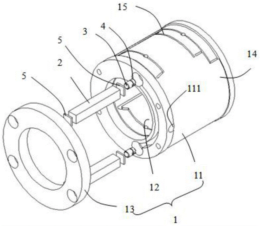
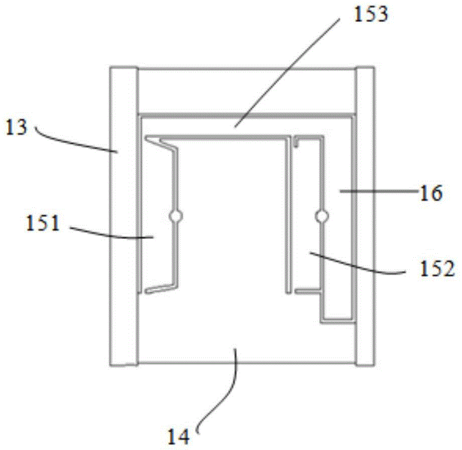
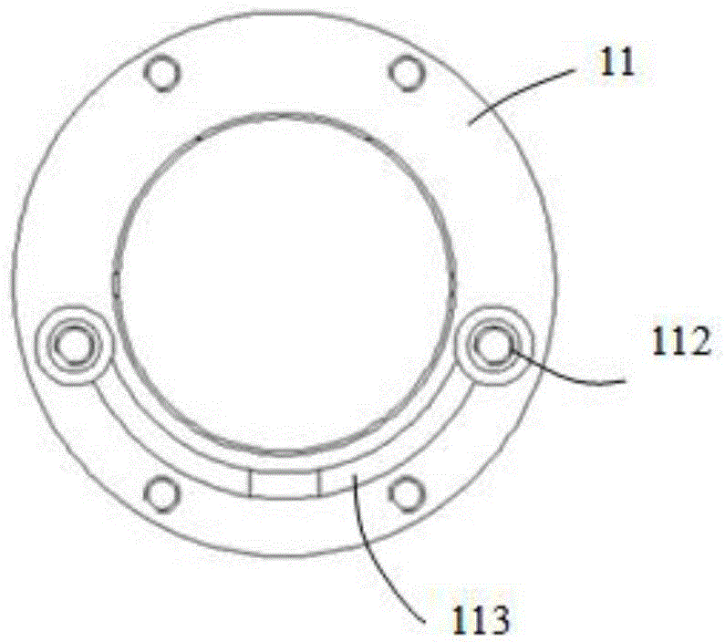
[0023] see Figure 1 to Figure 4 , an objective lens driving table described in a preferred embodiment of the present invention is used to fix the objective lens ring (not shown) of the microscope, which includes a hollow housing 1 and piezoelectric ceramics arranged on the hollow housing 1 2. The hollow housing 1 includes a housing part 11, a cavity 12 formed end to end through the housing part 11, and a hollow end cap 13 mounted on the housing part 11, and the housing part 11 includes a shell for cutting the housing. The base 14 and the hinge mechanism 15 formed by the part 11, the hinge mechanism 15 includes a follow-up part 151 and a moving part 152 arranged in paral...


PUM


Abstract

The invention belongs to the field of micro driving application and relates to an object lens driving table and specifically to an object lens driving table using a hinge mechanism to magnify output displacement. The object lens driving table is used for fixing an object lens ring and comprises a hollow housing and an actuating member disposed on the housing. The hollow housing comprises a housing portion and a chamber passing through the housing portion. The hinge mechanism is arranged on the housing portion and comprises a moving portion and a moving platform connected with the moving portion. The actuating member is abutted against the moving portion. The object lens ring is arranged in the chamber and is fixed to the moving platform. According to the object lens driving table, the hollow housing is provided; the hinge mechanism is disposed on the housing; the object lens ring is disposed on the moving platform of the hinge mechanism; and the actuating member is abutted against the moving portion of the hinge mechanism. Thus, the hinge mechanism magnifies the motion transmitted by the micro displacement of the actuating member in a gapless and uncoupled manner so as to effectively increase a motion magnification factor and guarantee size compactness.

Description

technical field [0001] The invention belongs to the field of micro-drive applications, and relates to an objective lens driving platform, in particular to an objective lens driving platform for amplifying the output displacement by using a hinge mechanism. Background technique [0002] At present, in biology, the optical microscope has always been a powerful tool for people to explore the microcosm, and people have continuously deepened their cognition of the microcosm by using it. The development of optical microscopes plays a key role in human understanding of life phenomena. With the continuous advancement of the level of science and technology, the application field of optical microscopes is expanding, and at the same time, its imaging quality is constantly improving. With the needs of social development, people's demand for the observation of the three-dimensional structure inside the microscopic sample is increasing, which puts forward extremely high requirements for ...

Claims


Application Information

Patent Timeline
IPC IPC(8): G02B21/24
Inventor 钟博文
Owner SUZHOU UNIV
Learn More