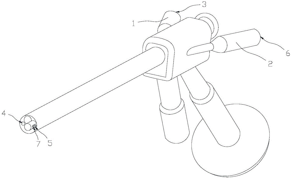
Endoscope and device with same
A technology for endoscopes and liquid outlet channels, applied in the field of endoscopes, can solve problems such as cumbersome operations, affect the operation process, increase operation time, etc., and achieve the effects of expanding the application range, enhancing safety, and improving flushing efficiency
- Summary
- Abstract
- Description
- Claims
- Application Information
AI Technical Summary
Problems solved by technology
Method used
Image
Examples
Embodiment 1
[0024] combine figure 1 As shown, the endoscope includes a liquid inlet channel 1 and a liquid outlet channel 2 .
[0025] There is a pulverizing part in the liquid outlet channel 2, which is used to crush the large particles entering the liquid outlet channel 2, so as to ensure that the liquid outlet channel 2 will not be blocked and realize continuous discharge of liquid.
[0026] In addition, large particles such as some tissues during the endoscopic operation can also be crushed by the crushing part, and then discharged from the liquid outlet channel 2, which is easy to operate and does not affect the operation time.
[0027] Preferably, the crushing part is detachably connected to the liquid outlet channel 2 .
[0028] Such as figure 2 and image 3 As shown, the crushing part includes a cutter head 7 and a driving part fixedly connected with the cutter head 7 .
[0029] The cutter head 7 is located at the liquid inlet 5 of the liquid outlet channel, such as figure 1...
Embodiment 2
[0043] combine Figure 4 As shown, the endoscope includes a liquid inlet channel 1 and a liquid outlet channel 2 .
[0044] A crushing part is provided in the liquid outlet channel 2 for crushing the large particles entering the liquid outlet channel 2, so that the liquid outlet channel 2 will not be blocked and the liquid can be continuously discharged.
[0045] The pulverizing component in Embodiment 2 can refer to the pulverizing component in Embodiment 1, and will not be described in detail here.
[0046] A No. 1 container 12 is connected to the liquid inlet 3 end of the liquid inlet channel, and a No. 2 container 13 is connected to the liquid outlet 6 end of the liquid outlet channel. A No. 1 pump 14 and a No. 2 pump 15 are arranged on the liquid inlet channel 1 and the liquid outlet channel 2 respectively.
[0047] The first container 12, the second container 13, and the first pump 14 and the second pump 15 are beneficial to increase the flow rate of the liquid in the ...
Embodiment 3
[0053] Embodiment 3 is a further preferred improvement made on the basis of Embodiment 2. For the parts not mentioned in Embodiment 3, reference can be made to Embodiment 2.
[0054] Such as Figure 5 As shown, the No. 1 container 12 is configured with a No. 1 metering sensor 18 , and the No. 2 container 13 is configured with a No. 2 metering sensor 19 . Each metering sensor can be selected from a sensor capable of measuring the weight or volume of the working fluid in the container.
[0055] The No. 1 pump 14 and the No. 2 pump 15 are equipped with a central controller 20 capable of controlling the operating states of the pumps. The No. 1 metering sensor 18 and the No. 2 metering sensor 19 are respectively connected to the central controller 20 .
[0056] In the above method, a No. 1 pressure sensor 21 can also be provided on the liquid inlet passage 1 between the No. 1 pump 14 and the liquid outlet 4 ends, and a pressure sensor 21 can be arranged on the liquid outlet betwe...
PUM
 Abstract
Description
Claims
Application Information
 - R&D
- Intellectual Property
- Life Sciences
- Materials
- Tech Scout
- Unparalleled Data Quality
- Higher Quality Content
- 60% Fewer Hallucinations
Browse by: Latest US Patents, China's latest patents, Technical Efficacy Thesaurus, Application Domain, Technology Topic, Popular Technical Reports.
© 2025 PatSnap. All rights reserved.Legal|Privacy policy|Modern Slavery Act Transparency Statement|Sitemap|About US| Contact US: help@patsnap.com


