
A machine tool spindle lubricating oil system with cooling function

A technology of machine tool spindle and lubricating oil, applied in manufacturing tools, metal processing equipment, metal processing mechanical parts, etc., can solve the problems of poor heat dissipation, insufficient lubrication, and inability to re-use, avoid rapid outflow, and facilitate installation. and the effect of replacement

Inactive Publication Date: 2017-04-19
SUZHOU YASIKE PRECISION CNC CO LTD
View PDF9 Cites 0 Cited by
  • Summary
  • Abstract
  • Description
  • Claims
  • Application Information

AI Technical Summary

Problems solved by technology

Among the three lubrication methods, the first grease lubrication is the simplest lubrication method, which is suitable for low-speed spindles, and can be used for several years at a time with low cost; the disadvantage is that the amount of lubricating oil cannot be adjusted, and the lubricating oil should be replaced after it is contaminated. Difficult, high heat generation, poor heat dissipation, not conducive to high speed
The second type of thin oil lubrication is the most commonly used lubrication method at present. It is characterized in that the lubricating oil can be recycled; the disadvantage is that it is difficult to control the amount of lubricating oil. Spindle speed, suppressing the spindle speed, the amount of oil is too small, the lubrication is not sufficient, and the bearing heat cannot be brought out
The third is oil mist lubrication. This kind of lubrication method is that the gas atomizes the lubricating oil and sends it to the bearing to lubricate the spindle bearing. Features: high spindle speed and low heat generation, it is a better method; disadvantages Yes: Since the oil is provided by the lubricator, the amount of oil is small, which is not suitable for large-scale machine tools, and the oil cannot be fully recovered, nor can it be reused, and the oil mist will cause great environmental pollution
This method can reduce fuel consumption, but the control process of this method is complicated, and the oil inlet and outlet conditions of each oil circuit need to be controlled separately, and if one or part of the oil circuits fails, or one or part of the oil circuits Failure to detect and repair valve failures in time will seriously affect the operation of the entire machine tool, and the cost of regular maintenance is high, and the application is limited

Method used


Image

  • A machine tool spindle lubricating oil system with cooling function
  • A machine tool spindle lubricating oil system with cooling function
  • A machine tool spindle lubricating oil system with cooling function

Examples


Embodiment Construction

[0025] The invention will be further explained below in conjunction with the accompanying drawings and specific embodiments. It should be understood that the following specific embodiments are only used to illustrate the invention but not to limit the scope of the invention.

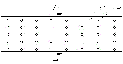
[0026] figure 1 It is a structural schematic diagram of the invention. It can be seen from the accompanying drawings that this kind of machine tool spindle lubricating oil system with cooling function includes a main shaft body, and the outer shaft body 6 of the main shaft is provided with several lubricating oil holes 2. The oil flows out from the lubricating oil hole 2 from the main shaft body and soaks into the surface of the main shaft body to lubricate the main shaft body.

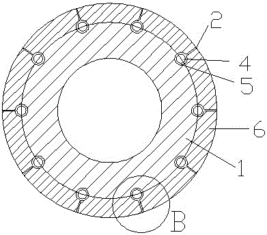
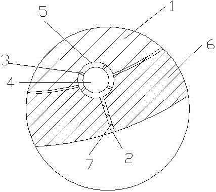
[0027] figure 2 yes figure 1 A-A sectional view in , combined with the accompanying drawings, it can be seen that the main shaft body includes a main shaft inner shaft body 1 and a main shaft outer shaft body 6, and the main...


PUM


Abstract

A machine tool spindle lubricating system with the cooling function comprises a spindle body composed of an inner spindle body and an outer spindle body. The sleeved contact faces of the outer spindle body and the inner spindle body are provided with multiple semicircular concave grooves of the same size. The semicircular concave grooves of the outer spindle body and the inner spindle body correspond to each other and are matched with each other to form multiple lubricating oil cavity pipelines. Cooling pipelines are arranged in the lubricating oil cavity pipelines and penetrate through the axial center lines of the corresponding lubricating oil cavity pipelines. Multiple lubricating oil holes are formed in the outer spindle body. Each lubricating oil hole is communicated with the corresponding lubricating oil cavity pipeline. The periphery of the spindle body can be fully lubricated through lubricating oil and the lubricating oil and the spindle body can be cooled through the cooling pipelines.

Description

technical field [0001] The invention relates to a machine tool spindle lubricating oil system with cooling function, which belongs to the technical field of machine tool spindles. Background technique [0002] A general machine tool spindle device includes a gear box, a machine tool spindle, bearings and a labyrinth seal ring. The machine tool spindle 2 is installed in the gear box, and a plurality of bearings are installed on the machine tool spindle. Type sealing ring. The traditional method of lubricating the spindle bearings of machine tools is to fill the bearings with high-grade grease. After long-term use, the labyrinth seal ring wears and the gap increases. When the machine tool is cutting, the coolant will enter the bearing along the spindle, and the high-grade grease will Saponification deterioration reduces the high temperature resistance and adhesion ability of high-grade lubricating grease, making the lubrication of the bearing unguaranteed, causing the precisi...

Claims


Application Information

Patent Timeline
Patent Type & Authority Patents(China)
IPC IPC(8): B23Q11/12B23B19/02
CPCB23Q1/70B23Q11/12
Inventor 马峻孙建明
Owner SUZHOU YASIKE PRECISION CNC CO LTD
Learn More