
Semi-independent suspension with inclined leaf springs

A semi-independent, leaf spring technology, applied in the direction of leaf springs, springs, springs/shock absorbers, etc., can solve the problem of poor reliability and load-carrying capacity of semi-independent leaf spring suspension, mutual influence of wheel jump on both sides, and maximum wheel rotation angle To achieve the effect of improving anti-rolling ability, improving wheel alignment parameters, and facilitating handling stability

Active Publication Date: 2015-09-09
TSINGHUA UNIV
View PDF7 Cites 5 Cited by
  • Summary
  • Abstract
  • Description
  • Claims
  • Application Information

AI Technical Summary

Problems solved by technology

[0005] The purpose of the present invention is to solve the problem that the traditional use of non-independent leaf spring suspension causes the bouncing of the wheels on both sides to interact with each other and the maximum wheel angle is limited, as well as the problems of poor reliability and bearing capacity of the semi-independent leaf spring suspension involved in the prior art. Provides a semi-independent suspension structure using oblique leaf springs to ensure the load-carrying capacity and reliability of the vehicle, increase the load-bearing center distance, reduce the variation of wheel alignment parameters, reduce abnormal wear of tires, and further improve the overall The anti-rolling ability of the vehicle is conducive to the stability of the vehicle operation

Method used


Image

  • Semi-independent suspension with inclined leaf springs
  • Semi-independent suspension with inclined leaf springs
  • Semi-independent suspension with inclined leaf springs

Examples


Embodiment Construction

[0025] The structural principles and specific implementation methods of the present invention will be further described below in conjunction with the accompanying drawings.

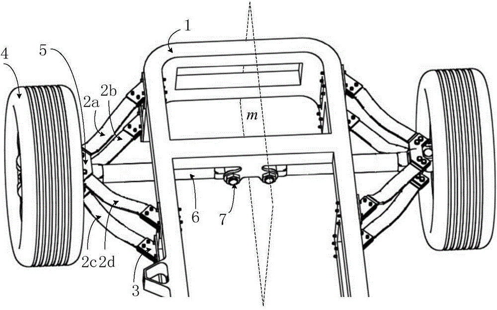
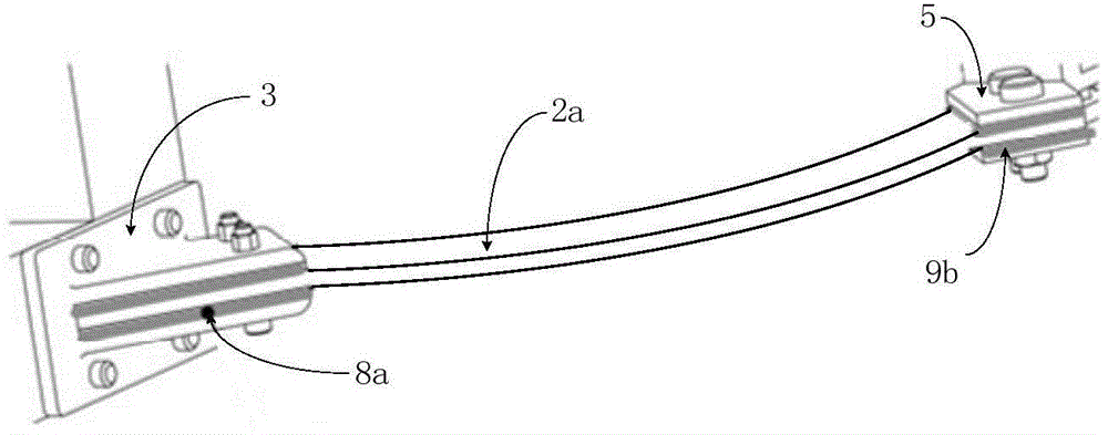
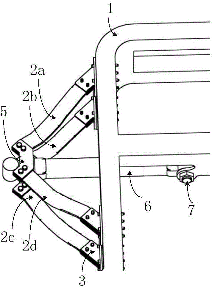
[0026] figure 1 It is an overall structure diagram of the present invention, and its overall structure is symmetrical about the m-plane (the m-plane is the longitudinal symmetrical center plane of the vehicle frame 1). Two semi-independent suspension devices, each semi-independent suspension device includes a leaf spring, an axle connecting member 5, a wheel 4 and a frame connecting member 3. One end of the half shaft 6 is connected to the vehicle frame 1 through the first 7 , and the other end is fixed to the axle connecting member 5 . The frame connecting member 3 is connected to the frame 1 by bolts, and the axle connecting member 5 is consolidated with the axle shaft 6; the leaf spring includes four inclined leaf springs, that is, the first inclined leaf spring 2a, the second inclined leaf spring Th...


PUM


Abstract

The invention provides a semi-independent suspension with inclined leaf springs and belongs to the field of automobile engineering. The suspension comprises a frame, a half axle, and two semi-independent suspension devices on the two sides of the frame; the suspension device on each side comprises four inclined leaf springs; the first and fourth inclined leaf springs are symmetrical about the half axle, while the second and third inclined leaf springs are symmetrical about the half axle; the line of intersection of longitudinal symmetrical central planes determined by the first and fourth inclined leaf springs is parallel to or collinear to the line of intersection of longitudinal symmetrical central planes determined by the second and third inclined leaf springs. According to the semi-independent suspension, the wheels on the left and right two sides are directly connected without a hard shaft, and therefore, the semi-independent suspension is better than a traditional non-independent leaf spring suspension in manipulation stability and driving smoothness. Meanwhile, four leaf springs connected in parallel are capable of effectively bearing and alleviating impact to achieve better bearing capability and reliability; in addition, the distance between the bearing centers on the two sides and the steering range of the wheels are increased, and therefore, the whole vehicle is enabled to be better in low-speed flexibility.

Description

technical field [0001] The invention relates to a suspension applied to vehicles, in particular to a semi-independent suspension for heavy-duty vehicles using leaf springs, and belongs to the field of automobile engineering. Background technique [0002] Suspension is a general term for related devices that ensure that there is an elastic connection between the wheel (or axle) and the frame (or body) and can transmit loads, ease shocks, dampen vibrations, and adjust the position of the car body during driving. The suspension directly determines the handling stability and ride comfort of the vehicle. [0003] The front axle structure of general commercial vehicles adopts non-independent leaf spring suspension system. Since the wheels on both sides of the non-independent leaf spring suspension are connected by hard shafts, the wheels on both sides interfere with each other when they jump, resulting in vehicle handling stability and smooth driving. At the same time, in order t...

Claims


Application Information

Patent Timeline
Patent Type & Authority Applications(China)
IPC IPC(8): B60G11/10
Inventor 赵景山刘向侯帅松
Owner TSINGHUA UNIV
Learn More