Vehicle lamplight mutual control system

A lighting control and vehicle technology, applied in vehicle components, optical signals, signaling devices, etc., can solve the problems of inability to prevent illegal use of lights, drivers not using high and low beams in accordance with regulations, etc., to achieve easy promotion, convenient installation and transformation, Guaranteed effect of accuracy

Inactive Publication Date: 2015-09-09
大同煤炭职业技术学院
View PDF9 Cites 3 Cited by
  • Summary
  • Abstract
  • Description
  • Claims
  • Application Information

AI Technical Summary

Problems solved by technology

However, in actual driving, some drivers do not use high and low beams according to the regulations, and driving bad habits such as not driving lights at night have caused many traffic accidents.
The existing car light control system requires human operation, so the phenomenon of illegal use of car lights cannot be eliminated

Method used


Image

  • Vehicle lamplight mutual control system
  • Vehicle lamplight mutual control system

Examples


Embodiment Construction

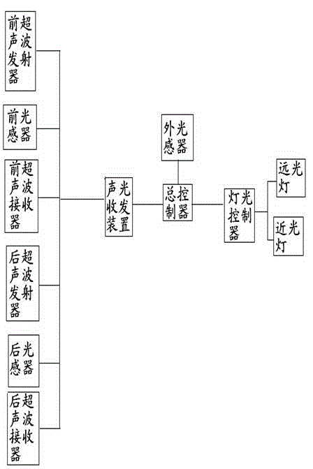
[0019] Such as Figure 1 Shown: After the vehicle is ignited, when the light intensity received by the external light sensor is lower than its light intensity setting value, the master controller sends an instruction to the light controller to turn on the dipped beam, and the sound and light transceiver device starts to work at the same time. When the light intensity received by the front light sensor or the rear light sensor is higher than its light sensitivity setting value, it proves that the other vehicle that is passing or the overtaking vehicle behind has not turned off the high beam. At this time, the front ultrasonic transmitter or rear ultrasonic The transmitter sends a signal, and when the front ultrasonic receiver of the opposite vehicle receives this signal, the master controller of the opposite vehicle sends an instruction to its light controller to turn off its high beam. When the front ultrasonic receiver or the rear ultrasonic receiver receives the signal f...


PUM


Abstract

A vehicle lamplight mutual control system comprises an acousto-optic transmitting and receiving device, an external light sensor, a total controller and a lamplight controller. The acousto-optic transmitting and receiving device is provided with a front ultrasonic wave emitter, a front ultrasonic wave receiver, a front light sensor, a rear ultrasonic wave emitter, a rear ultrasonic wave receiver, a rear light sensor and a vacuum cavity shell. The acousto-optic transmitting and receiving device is connected with the total controller and is controlled by the total controller. The external light sensor is connected with the total controller and is controlled by the total controller. The lamplight controller is connected with the total controller and is connected by the total controller. Automatic operation of vehicle lamplight use is achieved through mutual control, and bad habits and faults of manual operation are prevented. An ultrasonic wave is used and taken as an information transmission medium, and directivity of signal transmission is ensured. The acousto-optic transmitting and receiving device is provided with the vacuum cavity shell, and guarantees emitting and receiving accuracy of an acousto-optic signal. The vehicle lamplight mutual control system is low in cost, convenient to install and reform, and easy to popularize.

Description

technical field [0001] The invention relates to a lighting control system, in particular to a vehicle lighting mutual control system. Background technique [0002] When driving at night, the use of vehicle lights is particularly important, and the use of far and near lights is related to driving safety. Traffic regulations clearly stipulate that when meeting cars at night, both vehicles should turn off their high beams, and when overtaking, the vehicles behind should turn off their high beams. However, in actual driving, some drivers do not use high and low beams according to the regulations, and driving bad habits such as not driving lights at night have caused many traffic accidents. Existing car light control systems all need human operation, so the phenomenon of illegal use of car lights cannot be eliminated. Contents of the invention [0003] The object of the present invention is to provide a vehicle light mutual control system that can automatically turn off the h...

Claims


Application Information

Patent Timeline
Patent Type & Authority Applications(China)
IPC IPC(8): B60Q1/14
Inventor 陈永彪
Owner 大同煤炭职业技术学院
Why Eureka
Try Eureka