Selective plating fixture

A technology of selective plating and fixtures, which is applied in the electrolytic process and electrolytic components, etc., can solve the problems of inaccurate selective plating control in the electroplating area, unsatisfactory structural design, and large consumption of potion, so as to improve current distribution and electroplating efficiency. Effect of improving selective plating efficiency and reducing plating production cost

Inactive Publication Date: 2015-09-09
KUNSHAN YIDING IND TECH CO LTD
View PDF3 Cites 7 Cited by
  • Summary
  • Abstract
  • Description
  • Claims
  • Application Information

AI Technical Summary

Problems solved by technology

[0003] In the existing electroplating equipment, the selective plating device used in the electroplating production line, during the selective plating process of the terminal through the strip, due to poor electrical conductivity, the plating layer is poor or cannot be plated or the appearance is poor, resulting in a decline in the quality of the electroplating and excessive chemical consumption. Large, resulting in serious waste of precious metals; uneven coating, low product output, high cost, and poor quality
[0004] In all electroplating production lines, the disadvantages of the selective plating fixtures are: due to the unsatisfactory structural design, the selective plating control of the electroplating area is not accurate; the quality of the electroplating at the production port is reduced; the consumption of potion is large, which leads to serious waste of precious metals and increases the electroplating production. cost

Method used


Image

  • Selective plating fixture
  • Selective plating fixture
  • Selective plating fixture

Examples


Embodiment Construction

[0024] The following will clearly and completely describe the technical solutions in the embodiments of the present invention with reference to the accompanying drawings in the embodiments of the present invention. Obviously, the described embodiments are only some, not all, embodiments of the present invention. Based on the embodiments of the present invention, all other embodiments obtained by persons of ordinary skill in the art without creative efforts fall within the protection scope of the present invention.

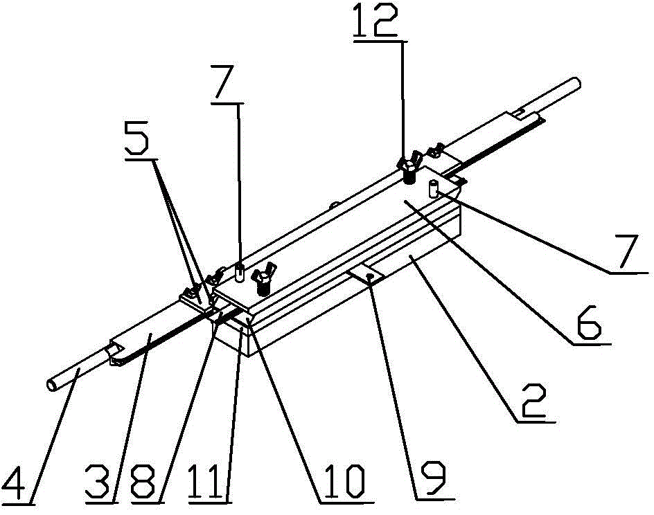
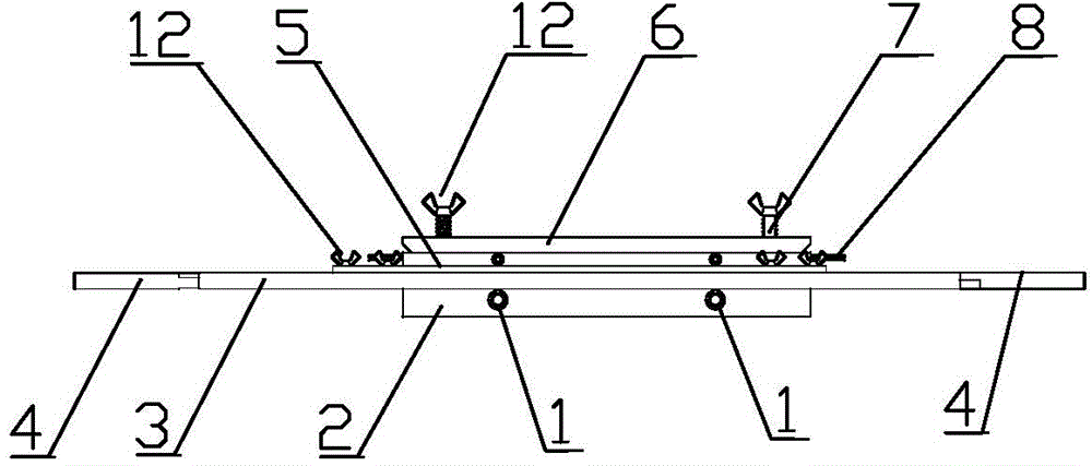
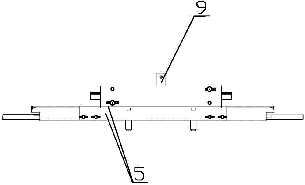
[0025] according to figure 1 , figure 2 , image 3 with Figure 4 , the present invention provides a selective plating jig, comprising a liquid inlet pipe 1, a rear cover 2, a cathode plate 3, a cathode handle 4, a cathode fixing block 5, a pressure plate 6, a guide post 7, a strip 8, an anode 9, a Material plate 10, liquid leakage plate 11, butterfly bolt 12.

[0026] Two liquid inlet pipes 1 are arranged on the rear side of the rear cover 2, and the liquid i...


PUM


Abstract

The invention discloses a selective plating fixture which comprises a rear cover, a cathode plate, cathode fixing blocks, a pressing plate, guide posts, a material strap, an anode, a material passing plate and a liquid leakage plate, wherein the liquid leakage plate is arranged on the rear cover; the material passing plate is arranged on the liquid leakage plate; the anode is arranged between the liquid leakage plate and the material passing plate; the pressing plate is arranged above the material passing plate; the pressing plate and the material passing plate are elastically connected through butterfly bolts and springs; the guide posts are arranged between the pressing plate and the material passing plate; the vertical cathode fixing block and the material passing plate are fixedly screwed; the horizontal cathode fixing block and the cathode plate are fixedly screwed; cathode handles are correspondingly arranged at two ends of the cathode plate; the material strap horizontally passes through a part between the material passing plate and the pressing plate and is arranged between the material passing plate and the pressing plate. According to the selective plating fixture disclosed by the invention, a selective plating structure is optimized, a titanium material is used as an anode base material, and the surface of the titanium material is coated with iridium, so that current distribution and plating efficiency are improved, the control precision of a selective plating area is improved, the plating quality is improved, the consumption of potion is reduced, precious metals are saved, the plating production cost is reduced, and the selective plating efficiency is improved.

Description

technical field [0001] The invention relates to the field of selective electroplating technical equipment, in particular to a selective plating jig. Background technique [0002] With the rapid development of electronic products, electroplating processing of electronic products is also widely used, and the requirements for electroplating products are also constantly increasing, especially for precious metal electroplating. Due to the expensive liquid used, the control of use and consumption has a great impact on production costs. large, and has received great attention from the industry. [0003] In the existing electroplating equipment, the selective plating device used in the electroplating production line, during the selective plating process of the terminal through the strip, due to poor electrical conductivity, the plating layer is poor or cannot be plated or the appearance is poor, resulting in a decline in the quality of the electroplating and excessive chemical consu...

Claims


Application Information

Patent Timeline
IPC IPC(8): C25D5/02C25D17/08
Inventor 周爱和
Owner KUNSHAN YIDING IND TECH CO LTD
Why Eureka
Try Eureka