
Method and device for operating an open-end rotor spinning machine

A rotor spinning machine, free end technology, applied in the directions of free end spinning machine, spinning machine, continuous winding spinning machine, etc., can solve problems such as difficulty in fiber sliver, and achieve the effect of optimizing yarn quality

Active Publication Date: 2015-09-09
SAURER GERMANY GMBH & CO KG
View PDF10 Cites 2 Cited by
  • Summary
  • Abstract
  • Description
  • Claims
  • Application Information

AI Technical Summary

Problems solved by technology

On the other hand, due to sometimes very large drafts from sliver to yarn, sliver defects extend very large yarn lengths, making it more difficult to determine sliver fluctuations by yarn clearers

Method used


Image

  • Method and device for operating an open-end rotor spinning machine
  • Method and device for operating an open-end rotor spinning machine
  • Method and device for operating an open-end rotor spinning machine

Examples


Embodiment Construction

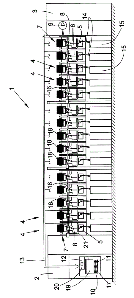
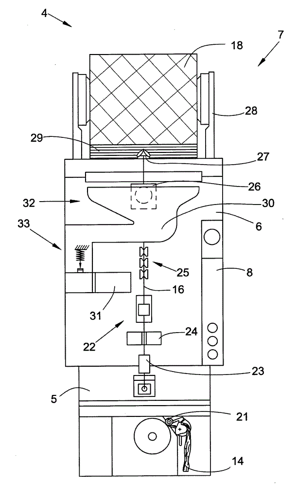
[0036] figure 1A front view of the open-end rotor spinning machine 1 is shown schematically. The open-end rotor spinning machine 1 has a plurality of substantially autonomous workstations 4 arranged between two end frames 2 and 3 . The end frames 2 and 3 of the open-end rotor spinning machine 1 (not shown in more detail as they are known) are provided by continuous supply and disposal channels (e.g. Spinning device 5 supplying vacuum channel for spinning vacuum, electrical channel for bus system 13 and cable channel for supplying electrical energy to workstation 4) connection. The yarn forming and winding mechanisms of the workstation 4 are fixed on these supply and disposal channels by means of the workstation housing 6 .

[0037] The workstation housings 6 releasably arranged on the supply and disposal channel each have, for example, a spinning device 5 , a winding device 7 and a workstation-specific control mechanism, a so-called workstation computer 8 .

[0038] The neg...


PUM


Abstract

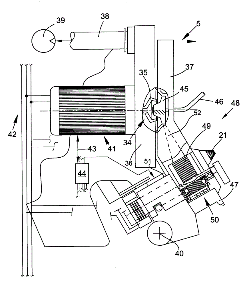
The present invention relates to a method and device for operating an open-end spinning machine (1). The device comprises a workstation (4), an open end yarning device (5) for producing lines (16), a wrapping device (7) for producing wrapping tubes (18) and a yarn cleaning device (24) for monitoring the horizontal size or quality of lines (16). The open end yarning device (5) is equipped with a loosening rod (49), which is provided with a motor driving apparatus (50). The invention further relates to an open end spinning machine.

Description

technical field [0001] The invention relates to a method for operating a workstation of an open-end rotor spinning machine with an open-end spinning device for a production line, a winding device for producing cross-wound bobbins and a yarn clearer for monitoring the transverse dimension or quality of the thread, the open-end spinning device is equipped with opening rollers with individual drives by electric motors. The invention also relates to an open-end rotor spinning machine for carrying out the method described above. Background technique [0002] Open-end rotor spinning machines are already known and generally comprise a large number of similar workstations arranged next to each other in a row. Each of these workstations has both a spinning device and a winding device on which the fiber sliver fed into the spinning pot is spun into yarn and wound to form a cross-wound bobbin. [0003] In order to achieve the above-mentioned purpose, the fiber sliver that has been fe...

Claims


Application Information

Patent Timeline
Patent Type & Authority Applications(China)
IPC IPC(8): D01H13/14D01H4/08D01H4/32B65H63/06
CPCD01H4/44D01H13/22D01H4/32D01H4/08
Inventor H·佩赫利万德特勒夫·舍尔特
Owner SAURER GERMANY GMBH & CO KG
Learn More