
Rail vibration absorbing device for rail transit

A rail transit and rail technology, applied in the field of rail transit, can solve problems such as driving safety hazards, aggravated vehicle vibration, and potential safety hazards, and achieve the effects of reducing maintenance costs, reducing vibration and noise pollution, and improving driving safety

Active Publication Date: 2017-03-01
洛阳双瑞橡塑科技有限公司
View PDF6 Cites 0 Cited by
  • Summary
  • Abstract
  • Description
  • Claims
  • Application Information

AI Technical Summary

Problems solved by technology

[0006] (2) The wavy wear of the rail surface poses a hidden danger to driving safety
[0007] Rail transit has very strict requirements on the operating conditions of trains. The serious unevenness of the rail surface prevents the high-speed wheels from fitting the rails well, posing safety hazards.
Rail corrugation causes rail and vehicle vibration to intensify, resulting in damage to rail safety fastening parts (broken springs) and a high replacement rate of locomotive and rolling stock parts, which increases vehicle maintenance costs
On the line, the transportation is often interrupted due to rail corrugation, disrupting the operation plan and causing unnecessary economic losses
[0008] (3) Increased track maintenance costs
In this type of structure, the rail waist on both sides of the rail is completely wrapped by the elastic body. In order to achieve the vibration absorption effect, the product is closely attached to the surface of the rail and has a certain clamping force, which makes the rigidity of the elastic body larger in the direction vertical to the rail waist. , there is a large constraint on the mass block. When the mass block is excited, it is difficult to generate low-order vibration in the direction vertical to the rail, that is, lateral vibration. The effect of controlling the lateral vibration of the rail, reducing the impact of the wheel and rail, and controlling the wave wear

Method used


Image

  • Rail vibration absorbing device for rail transit
  • Rail vibration absorbing device for rail transit
  • Rail vibration absorbing device for rail transit

Examples


Embodiment Construction

[0031] The present invention is described in conjunction with accompanying drawing and specific embodiment:

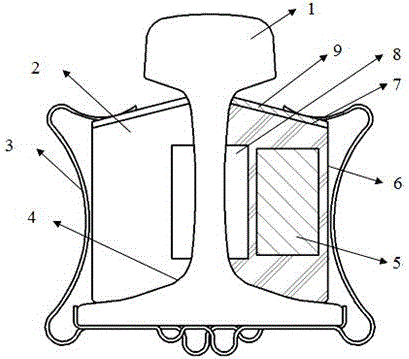
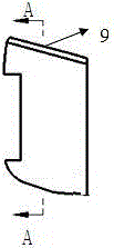
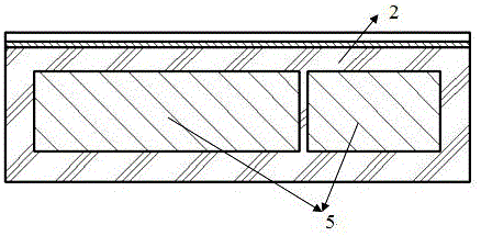
[0032] Such as figure 1 As shown, a rail vibration-absorbing device for rail transit, the rail vibration-absorbing device includes an elastic body 2, a mass 5 and an elastic fixing clip 3; the elastic body 2 is arranged on both sides of each steel rail 1 and Arranged along the longitudinal direction of the rail 1, the outline of the contact surface 4 between the elastic body and the rail is consistent with the outer surface of the rail 1; fit tightly figure 2 , image 3 , the mass block 5 is embedded in the elastic body 2 and arranged along the longitudinal direction of the elastic body 2; there is a cavity between the mass block 5 and the rail waist of the rail 1. In this embodiment, the The above-mentioned cavity is formed between the groove I8 arranged along the rail laying direction on the joint surface of the elastic body and the rail waist and the rail waist,...


PUM


Abstract

The invention belongs to the technical field of rail transportation, and in particular relates to a rail vibration absorbing device for rail transportation. A proposed rail vibration absorbing device for rail transit includes an elastic body (2), a mass block (5) and an elastic fixing clip (3); there is a cavity between the mass block (5) and the rail waist of the rail (1); The rail vibration absorbing device is also provided with a rigid constrained layer (9), which is at least located between the upper end surface of the elastic body and the elastic fixing clip, so that the elastic fixing clip clamps the elastic body through the rigid constrained layer to disperse the elasticity. The pressure on the upper end and side of the body reduces the stress of the elastic body, which is beneficial to exert the elasticity of the elastic body, reduces the deformation of the elastic body in the vertical direction, reduces the constraint on the mass block, and increases the vibration of the elastic body in the lateral direction. The invention effectively controls the wheel-rail impact, reduces rail corrugation, reduces vibration and noise pollution, improves driving safety, and reduces track operation and maintenance costs.

Description

technical field [0001] The invention belongs to the technical field of rail transportation, and in particular relates to a rail vibration absorbing device for rail transportation. Background technique [0002] Rail transit has the advantages of fast speed, large capacity, low cost, comfort and safety, and little air pollution. Track and traffic safety are the key factors to ensure the long-term normal operation of trains. [0003] At present, with the long-term operation of trains on domestic rail transit lines, the wheel and rail vibration and noise radiation generated by the rolling contact impact excitation between the rail and the wheel have caused non-negligible environmental pollution and seriously affected the ride comfort; wheel-rail impact The excitation and track irregularities make the rail and the wheel produce unstable vibrations at different levels, resulting in the continuous development of wavy wear on the surface of the wheel and rail (referred to as rail co...

Claims


Application Information

Patent Timeline
Patent Type & Authority Patents(China)
IPC IPC(8): E01B19/00E01B9/62
CPCE01B9/62E01B19/003
Inventor 白健张喆玉王安斌
Owner 洛阳双瑞橡塑科技有限公司
Learn More