Small gas-gas injection optical transparent combustion device

An optically transparent, combustion device technology, used in jet propulsion devices, rocket engine devices, machines/engines, etc., can solve problems such as interference and data accuracy errors, and achieve the effect of facilitating replacement, reducing glass damage, and simplifying the ignition process

Active Publication Date: 2015-09-09
BEIHANG UNIV
View PDF4 Cites 13 Cited by
  • Summary
  • Abstract
  • Description
  • Claims
  • Application Information

AI Technical Summary

Problems solved by technology

However, due to its unavoidable characteristics of interference with the original flow field, there is a certain error in the data accuracy

Method used


Image

  • Small gas-gas injection optical transparent combustion device
  • Small gas-gas injection optical transparent combustion device
  • Small gas-gas injection optical transparent combustion device

Examples


Embodiment Construction

[0029] The present invention will be further described in detail below in conjunction with the drawings.

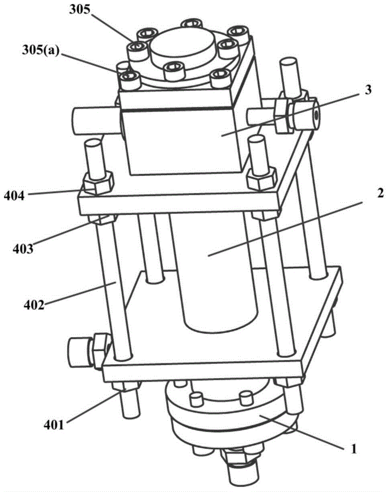
[0030] The invention provides a small gas-gas injection optically transparent combustion device, such as figure 1 As shown, the described device includes a combustion chamber head cavity 1, a transparent combustion chamber 2 and a combustion chamber tail 3. The head cavity 1 and the tail 3 of the combustion chamber fix the transparent combustion chamber 2 in the middle by four evenly distributed screws 402. The two ends of the screw 402 are respectively connected with four hexagonal nuts A401 and four hexagonal nuts C404 to apply a pre-tightening force to the transparent combustion chamber 2 between the combustion chamber head cavity 1 and the combustion chamber tail 3 to reach the transparent combustion chamber 2 The sealing requirements. Considering that the test device is in a vertical state during actual use, the transparent combustion chamber 2 is in danger of rupture ...


PUM


Abstract

The invention discloses a small gas-gas injection optical transparent combustion device and suitable for the field of multi-optical diagnosis technology. The combustion device comprises a combustion chamber head cavity, a transparent combustion chamber and a combustion chamber tail. The transparent combustion chamber is fixed between the combustion chamber head cavity and the combustion chamber tail by four uniformly distributed screws. Two ends of each of the screws are cooperatively connected with one hexagonal nut A and one hexagonal nut C so as to impose pretightening force on the transparent combustion chamber, thereby achieving sealing requirements in the transparent combustion chamber. Hexagonal nuts B are cooperatively connected to the screws under a combustion chamber pressing cover and are used for supporting the combustion chamber pressing cover. The transparent combustion device performs comprehensive detection for combustion states, and helps people to deep research combustion mechanism. According to the similarity principle of combustion, research principles of combustion mechanism in a low pressure environment are established, so combustion condition in a high pressure condition can be predicted.

Description

Technical field [0001] The invention relates to a gas-gas injection combustion device suitable for multi-optical diagnosis. More specifically, it refers to a transparent combustion device suitable for multi-optical diagnosis of a rocket engine with small thrust, low flow and low combustion chamber pressure . Background technique [0002] The full-flow supplemental combustion cycle engine is a new type of cycle method for liquid rocket engines, in which gas-gas injector combustion technology is one of its core technologies. During the test, the combustion process needs to be accurately measured in multiple directions to obtain accurate and credible performance parameters, which facilitates more research on the nature of the combustion mechanism. [0003] The traditional combustion measurement device is a contact measurement method. Generally, the sensor probe is arranged in the area to be measured or in the flow field. After a certain period of time reaches equilibrium, the paramet...

Claims


Application Information

Patent Timeline
Patent Type & Authority Applications(China)
IPC IPC(8): F02K9/62F02K9/60F02K9/96
Inventor 俞南嘉戴健蔡国飙
Owner BEIHANG UNIV
Why Eureka
Try Eureka