Needle Roller Mounting Structure for Needle Roller Bearings

A technology for needle roller bearings and installation structures, which is applied in the direction of bearing components, shafts and bearings, mechanical equipment, etc. It can solve the problems of unsmooth rotation of needle rollers, poor stability, and easy wear and tear of needle rollers, and achieve simple structure and Good lubrication and good installation stability

Active Publication Date: 2018-02-09
浙江昕兴科技有限公司
View PDF7 Cites 0 Cited by
  • Summary
  • Abstract
  • Description
  • Claims
  • Application Information

AI Technical Summary

Problems solved by technology

[0004] The above-mentioned scheme has improved some problems of the prior art to a certain extent, but the scheme also has at least the following defects: poor stability, not smooth enough rotation of the needle roller, and easy wear and tear of the needle roller

Method used


Image

  • Needle Roller Mounting Structure for Needle Roller Bearings
  • Needle Roller Mounting Structure for Needle Roller Bearings
  • Needle Roller Mounting Structure for Needle Roller Bearings

Examples


Embodiment 1

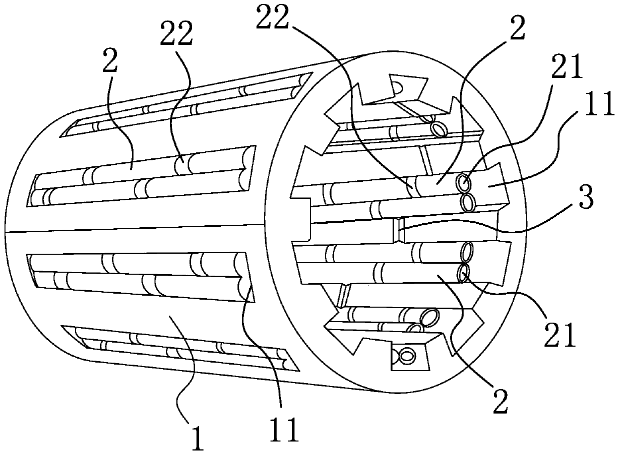
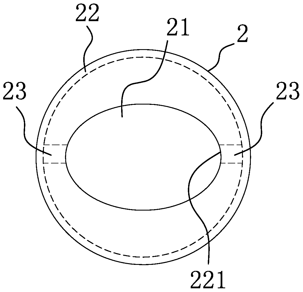
[0023] Such as Figure 1-2 As shown, the needle roller installation structure of the needle roller bearing includes a cylindrical needle roller cage body 1, and a plurality of retaining grooves 11 extending axially along the needle roller cage body 1 are provided in the circumferential direction of the needle roller cage body 1. Each holding groove 11 is provided with at least two needle rollers 2 side by side in sequence. The needle rollers 2 are axially arranged in the holding groove 11 and two adjacent needle rollers 2 are arranged against each other. The needle rollers 2 are Cylindrical, in the needle roller body 2 there is a non-circular through hole 21 extending axially along the needle roller body 2 and having a cross-section with at least two protrusions. Annular grooves 22, the annular grooves 22 are distributed sequentially along the axial direction of the needle roller body 2 and the annular grooves 22 on two adjacent needle roller bodies 2 are alternately arranged ...

Embodiment 2

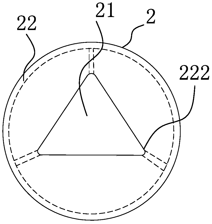
[0029] Such as image 3 As shown, the structure, principle and implementation steps of this embodiment are similar to those of Embodiment 1, the difference is that the cross section of the through hole 21 in this embodiment is a polygon with at least three corners 222. The corner 222 forms the above-mentioned protrusion, and the number of oil holes 23 on each annular groove 22 is at least three, and the oil holes 23 are respectively arranged on the side of the annular groove 22 that is close to the corner 222 in the circumferential direction, That is, there are at least three oil holes 23 on the annular groove 22 here, and they are respectively arranged on each corner of the polygonal through hole 21 .


PUM


Abstract

The invention relates to a needle roller installation structure of a needle roller bearing. It solves the technical problems such as the poor installation stability of the existing needle roller bearings and the like. It includes a needle roller cage body and a holding groove. There are at least two needle roller bodies in each holding groove. The body is cylindrical, and there is a non-circular through hole extending along the axial direction of the needle body in the needle body and having a cross-section with at least two protrusions, and several annular grooves are arranged on the circumferential outer side of the needle body , the annular grooves are distributed sequentially along the axial direction of the needle roller body and the annular grooves on two adjacent needle roller bodies are alternately arranged one by one. oil hole. The advantages are: more reasonable design, simple structure, good installation stability, less shaking, smooth needle rotation, less wear and tear, and good needle lubrication.

Description

technical field [0001] The invention belongs to the technical field of auto parts, and in particular relates to a needle roller installation structure of a needle roller bearing. Background technique [0002] Needle roller bearings are roller bearings with cylindrical rollers, which have a small cross-section relative to their diameter, and the bearings still have a high load-bearing capacity. Needle roller bearings are equipped with thin and long rollers, so the radial structure is compact , when the inner diameter size and load capacity are the same as other types of bearings, the outer diameter is the smallest, especially suitable for support structures with limited radial installation dimensions. Needle roller bearings mainly include inner and outer rings, and a cage with needle rollers is installed between the inner and outer rings. The main function of the cage is to separate the rolling elements, reduce mutual friction between the rolling elements and maintain the sta...

Claims


Application Information

Patent Timeline
Patent Type & Authority Patents(China)
IPC IPC(8): F16C43/06
Inventor 金文忠
Owner 浙江昕兴科技有限公司
Why Eureka
Try Eureka