Indicating light optical state automatic test method and system

An automatic test system and optical state technology, applied in the direction of testing optical performance, etc., can solve the problems such as the inability to accurately reflect the optical state of the indicator light, the inability to accurately obtain the flashing frequency of the indicator light, and increase the complexity of the hardware design, so as to achieve automatic testing. And the effect of evaluating, reducing test complexity, and complete test results

Inactive Publication Date: 2015-09-09
CSR ZHUZHOU ELECTRIC LOCOMOTIVE RES INST
View PDF5 Cites 17 Cited by
  • Summary
  • Abstract
  • Description
  • Claims
  • Application Information

AI Technical Summary

Problems solved by technology

There are two disadvantages in this type of method: a. due to the detection of the voltage or current of the indicator light, an electrical interface needs to be reserved on the hardware, which increases the complexity of hardware design and increases the cost of hardware manufacturing; b. because this test method is The status information of the indicator light is obtained indirectly through the voltage or current status information of the indicator light. In some cases, misjudgment may occur. For example, if only the indicator light is damaged but other electrical parts of the device are not damaged, the indicator light will eventually be On, off, or flashing at a certain frequency does not correspond to the voltage or current state information of the indicator light, so only the voltage or current state information of the indicator light cannot accurately reflect the final optical state of the indicator light
[0005] The second is the method of manual observation, which is to observe the optical state of the light on and off through the human eye, and then rely on the manual to judge the current working state of the equipment based on the observation results. Obviously, this method cannot accurately obtain the flickering frequency of the light

Method used


Image

  • Indicating light optical state automatic test method and system
  • Indicating light optical state automatic test method and system
  • Indicating light optical state automatic test method and system

Examples


Embodiment Construction

[0045] The present invention will be further described below in conjunction with the accompanying drawings and specific preferred embodiments, but the protection scope of the present invention is not limited thereby.

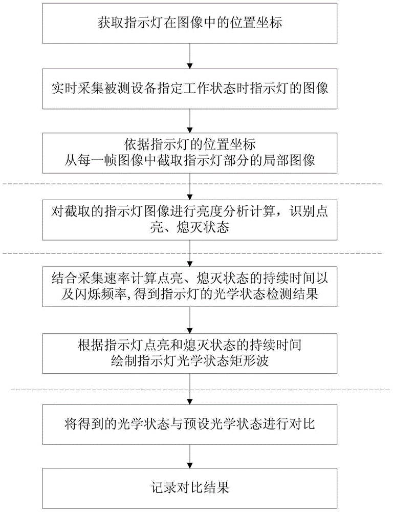
[0046] Such as figure 1 As shown, the automatic test method for the optical state of the indicator light in this embodiment, the steps include:

[0047] 1) Image acquisition: real-time acquisition of the image of the target indicator light when the device under test is in a specified working state at a preset acquisition rate;

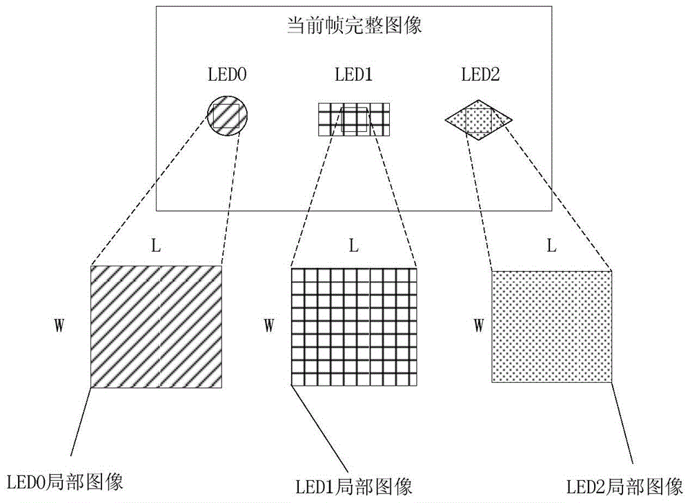
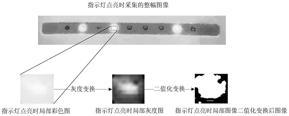
[0048] 2) Image processing and recognition: image processing is performed on each frame of image output in step 1), and the corresponding lighting and extinguishing states of the target indicator light in each frame of image are recognized;

[0049] 3) Optical state detection: Obtain the number of image frames that are continuously on or off in all identified frame images, and calculate the duration of the on state or off state, and the...


PUM


Abstract

The invention discloses an indicating light optical state automatic test method and system. The method includes the following steps that: 1) images of an indicating light is acquired in real time with preset acquisition rate when tested equipment is in a designated work status; 2) image processing is performed on each frame of acquired image, and corresponding lit and extinguished states of the indicating light in each frame of image are identified; 3) the lasting time of the lit state or the extinguished state and the frequency of flickering states formed by the alternation of the lit state or the extinguished state are calculated, so that an optical state detection result of the indicating light can be obtained; and 4) the optical state detection result is compared with a preset optical state, and whether the optical states of the indicating light accord with design requirements is judged according to a comparison result. The system includes a corresponding image acquisition module, an image processing and identification module, an optical state detection module and a test result analysis module. The indicating light optical state automatic test method and system of the invention have the advantages of simplicity in realization and high accuracy of test results. With the indicating light optical state automatic test method and system adopted, the optical state of the indicating light can be tested directly.

Description

technical field [0001] The invention relates to the technical field of indicator light testing, in particular to a method and system for automatically testing the optical state of an indicator light. Background technique [0002] At present, all kinds of electronic / electrical equipment are usually equipped with indicator lights in order to observe the working status of the equipment, and the indicator lights are lit or extinguished for a specific period of time according to the working status of the equipment, or alternately lit and extinguished at a certain frequency flashes to indicate the current working status of the device. The user can judge the current working state of the electronic / electrical equipment by observing the light on or off time of the indicator light or the optical state of a specific flicker frequency. [0003] In order to ensure that when the electronic / electrical equipment is actually running, the indicator light can correctly perform actions such as...

Claims


Application Information

Patent Timeline
Patent Type & Authority Applications(China)
IPC IPC(8): G01M11/02
Inventor 袁浩唐爱斌彭辉水黄旺李文波
Owner CSR ZHUZHOU ELECTRIC LOCOMOTIVE RES INST
Why Eureka
Try Eureka