Test piece guide-in mechanism of ceramic material heating thermal shock test box

A technology of impact test chamber and ceramic materials, which is applied in the direction of analyzing materials, instruments, measuring devices, etc., can solve the problems of long time, high temperature radiation of heating furnace, low efficiency, etc., and achieve the effect of accurate testing, avoiding mechanical shock and high efficiency

Active Publication Date: 2015-09-09
CHONGQING UNIV
View PDF5 Cites 9 Cited by
  • Summary
  • Abstract
  • Description
  • Claims
  • Application Information

AI Technical Summary

Problems solved by technology

[0004] 1. It takes a lot of time to install the test piece on the clamping mechanism and guide wire, and only one test piece can be clamped in one experiment, so the efficiency is relatively low;
[0005] 2. Since there is no special room temperature chamber designed to store the test piece before the thermal shock test, and the clamped test piece is relatively close to the heating furnace, it is easily affected by the high temperature radiation of the heating furnace;
[0006] 3. When the test piece enters the heating furnace, it falls directly onto the cushion in the way of free fall, which cannot avoid tiny mechanical shocks.
[0007] The above problems lead to large errors in the test process, resulting in the experimental results not being able to characterize the thermal shock resistance of ceramic materials, and the efficiency is low

Method used


Image

  • Test piece guide-in mechanism of ceramic material heating thermal shock test box
  • Test piece guide-in mechanism of ceramic material heating thermal shock test box
  • Test piece guide-in mechanism of ceramic material heating thermal shock test box

Examples


Embodiment Construction

[0016] Below in conjunction with accompanying drawing and embodiment the present invention will be further described:

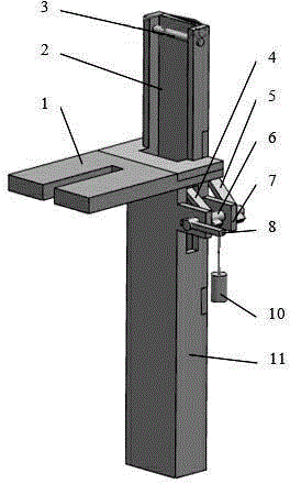
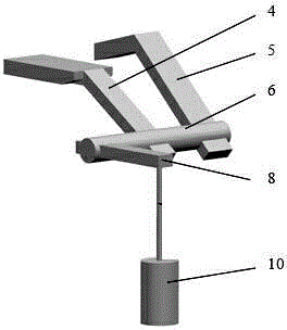
[0017] Such as figure 1 with figure 2 As shown, the present invention includes a guide cylinder 11, the upper side of the guide cylinder 11 is provided with a guide cylinder opening 2 for placing a test piece, and the lower end of the guide cylinder opening 2 is provided with a connecting lug 1 for fixing the guide cylinder 11. There are two opposite rotating shaft supports 7 on the side below the ear 1, and a rotating shaft 6 runs through the two rotating shaft supports 7. A baffle 4 is installed on the rotating shaft 6 of the guide cylinder 11, and the baffle 4 extends into the guide cylinder 11 from the notch on the side wall of the guide cylinder 11, and a counterweight suspension rod 8 is installed on the extension end of the rotation shaft 6 near the connecting lug side, and the counterweight suspension rod 8 is provided with a counterweight 10 at th...


PUM


Abstract

The invention discloses a test piece guide-in mechanism of a ceramic material heating thermal shock test box. The test piece guide-in mechanism comprises a guide cylinder. A guide cylinder opening for placing a test piece is formed in the lateral side of the upper portion of the guide cylinder. A connecting lug for fixing the guide cylinder is disposed at the lower end of the guide cylinder opening. Two opposite rotary shaft supports are disposed on the lateral side below the connecting lug. A rotary shaft penetrates the two rotary shaft supports. Two ends of the rotary shaft extends out of the two rotary shaft supports. A retaining piece is mounted on the rotary shaft between the two rotary shaft supports. The retaining piece extends into the guide cylinder through a slot in the lateral wall of the guide cylinder. The rotary shaft extending end close to the connecting lug side is provided with a counter weight hanging rod. The suspension end of the counter weight hanging rod is provided with counter weight. The other extending end, opposite to the counter weight hanging rod, of the rotary shaft is provided with a shifting piece. A suspension wire is disposed at the top end of the guide cylinder. The test piece guide-in mechanism has the advantages that a normal-temperature cavity isolated from a heating furnace can be built, and the test piece is prevented from being radiated by high temperature; mechanical shock of the test piece is avoided, heating-resistance thermal shock performance tests can be performed on multiple test pieces at the same time, and high efficiency is achieved.

Description

technical field [0001] The invention relates to a thermal shock resistance test device, in particular to a test piece introduction mechanism of a ceramic material thermal shock test box. Background technique [0002] Ceramic materials are widely used in the field of high-temperature structures due to their high melting point and excellent chemical and physical stability at high temperatures, such as thermal protection materials for hypersonic aircraft and hot ends of engines. However, ceramic materials have poor thermal shock resistance due to their brittleness. For ceramic materials used in high-temperature structures, especially in the field of aerospace, they are often damaged due to severe thermal shocks in the use environment. Therefore, it is very necessary and important to study the thermal shock resistance of ceramic materials. [0003] Chinese patent document CN104483224A disclosed "a test chamber for heating thermal shock of ceramic materials" on January 14, 2015...

Claims


Application Information

Patent Timeline
Patent Type & Authority Applications(China)
IPC IPC(8): G01N3/60G01N3/02
Inventor 李卫国张曦蓓麻建坐王如转李定玉张先贺方岱宁
Owner CHONGQING UNIV
Why Eureka
Try Eureka