Insulation test control module

A technology for insulation testing and control modules, which is applied in program control, electronic circuit testing, and dielectric strength testing. It can solve problems such as personal safety accidents, PCB circuit network damage, and affecting the brand image of flying probe testing machines. Improve personal safety protection performance, reduce the possibility of electric shock, and ensure the effect of insulation test efficiency

Active Publication Date: 2015-09-09
HANS CNC SCI & TECH
View PDF13 Cites 5 Cited by
  • Summary
  • Abstract
  • Description
  • Claims
  • Application Information

AI Technical Summary

Problems solved by technology

During the insulation test, if there is a short circuit between the adjacent networks of the PCB under test, the test needle is in micro-contact with the PCB under test at the moment before the test probe contacts the PCB network, and at the same time, the voltage of the test probe is instantaneous. change and discharge
Visually, there is a phenomenon of discharge and ignition, and the PCB circuit network is also damaged, and the tested PCB will even be burned, making the defective PCB irreparable, which will cause waste of production costs and additional compensation, affecting flight The brand image of the needle testing machine; at the same time, the test probe with high voltage is a potential danger during the movement process or system maintenance and debugging, and personal safety accidents are prone to occur

Method used


Image

  • Insulation test control module
  • Insulation test control module
  • Insulation test control module

Examples


Embodiment Construction

[0026] In order to facilitate the understanding of the present invention, the present invention will be described more fully below with reference to the associated drawings. Preferred embodiments of the invention are shown in the accompanying drawings. However, the present invention can be embodied in many different forms and is not limited to the embodiments described herein. On the contrary, these embodiments are provided to make the understanding of the disclosure of the present invention more thorough and comprehensive.

[0027] Unless otherwise defined, all technical and scientific terms used herein have the same meaning as commonly understood by one of ordinary skill in the technical field of the invention. The terms used herein in the description of the present invention are for the purpose of describing specific embodiments only, and are not intended to limit the present invention. .

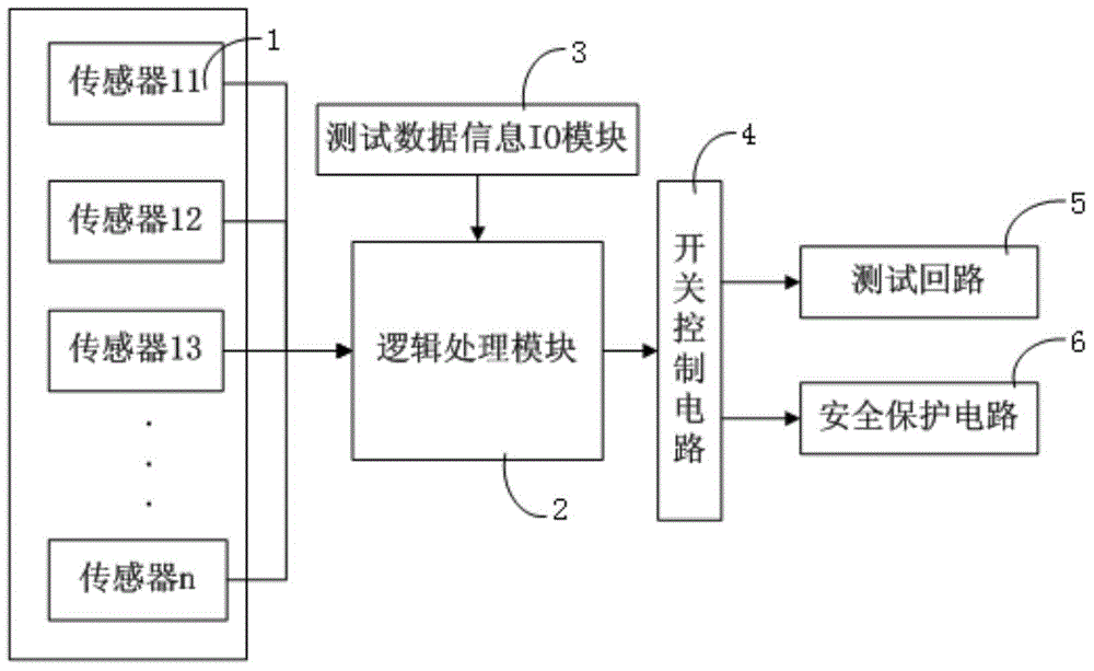
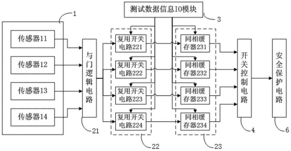
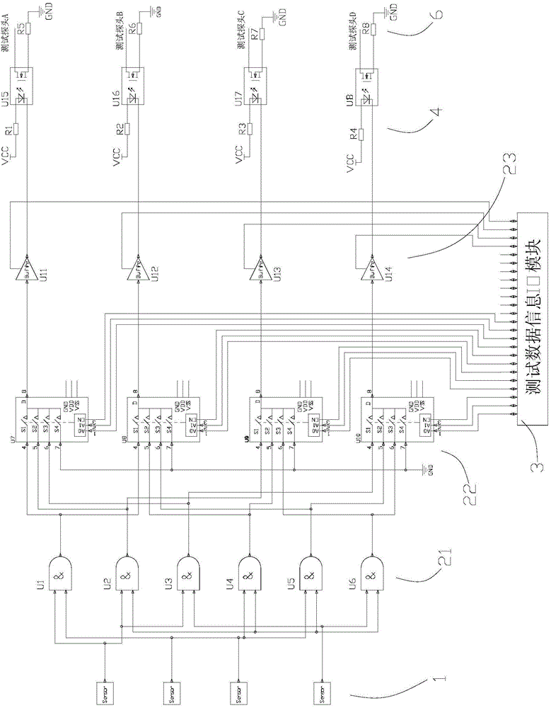
[0028] refer to Figure 1 ~ Figure 3 As shown, the present invention provides a ...


PUM


Abstract

The invention relates to the technical field of electronic measurement and discloses an insulation test control module. The insulation test control module comprises at least two contact detection sensors used for sensing whether a test probe of a flying-probe tester is stably contacted with a tested PCB and outputting level signals showing whether the test probe is stably contacted; a logic processing module connected with the contact detection sensors and used for receiving the level signals output by the contact detection sensors, carrying out AND logic processing on the level signals and outputting switch control signals; a test data information IO module connected with the logic processing module and used for providing insulation test control information; a switch control circuit connected with the logic processing module and used for receiving the switch control signals output by the logic processing module and controlling operation of the switch control circuit according to the switch control signals; and a safety protection circuit connected with the switch control circuit. The insulation test control module has the advantages of being high in test efficiency, and capable of eliminating the problem of sparking and improving personal safety.

Description

technical field [0001] The invention relates to the technical field of electronic measurement, and more specifically relates to a control module used in PCB high-voltage insulation testing. Background technique [0002] When the flying probe test electromechanical test system uses a DC high voltage test source to conduct insulation tests on the adjacent network of the PCB, in the state of the two test probes for the insulation test, one of the probes is a gate high voltage test source, and the other probe is is a circuit that is gated at zero voltage. In order to avoid the communication time of the upper computer / lower computer and the response time of the test execution circuit from affecting the overall test efficiency, the test often needs to select the probe combinations and probe states that need to be tested for insulation testing during the movement of the test probes. During the insulation test, if there is a short circuit between the adjacent networks of the PCB un...

Claims


Application Information

Patent Timeline
Patent Type & Authority Applications(China)
IPC IPC(8): G05B19/04G01R31/12G01R31/28
CPCG05B19/042G05B2219/25314
Inventor 黄俊华王星翟学涛杨朝辉高云峰
Owner HANS CNC SCI & TECH
Why Eureka
Try Eureka