CBUS data receiving device and CBUS data receiving method

A data receiving device and bus technology, applied in the direction of electrical digital data processing, instruments, etc., can solve the problems of wasting hardware resources, overhead, time consumption, etc., and achieve the effect of improving error detection efficiency and saving hardware logic resources

Active Publication Date: 2015-09-09
SHANGHAI HUAHONG INTEGRATED CIRCUIT
View PDF4 Cites 0 Cited by
  • Summary
  • Abstract
  • Description
  • Claims
  • Application Information

AI Technical Summary

Problems solved by technology

And generally, the check digit of the data packet with the check digit can be provided by software, but the disadvantage is that it consumes time and overhead, and the speed of hardware implementation is fast, but it wastes hardware resources to a certain extent.

Method used


Image

  • CBUS data receiving device and CBUS data receiving method
  • CBUS data receiving device and CBUS data receiving method
  • CBUS data receiving device and CBUS data receiving method

Examples


Embodiment Construction

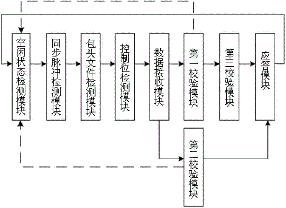
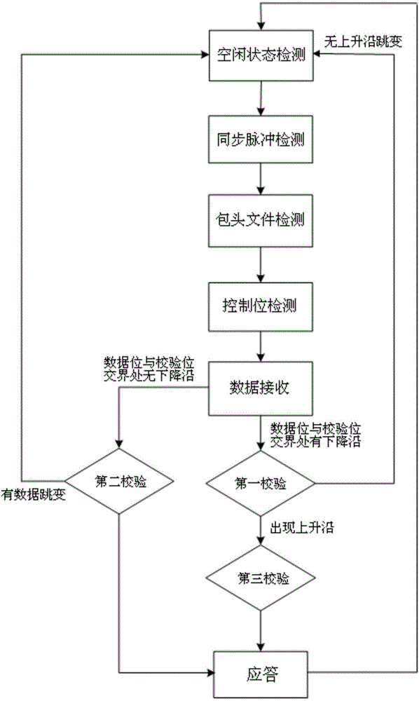
[0036] see figure 1 As shown, the CBUS bus data receiver device includes: an idle state detection module, a synchronous pulse detection module, a packet header file detection module, a control bit detection module, a data receiving module, a first verification module, A second verification module, a third verification module, and a response module. image 3 It is a flowchart of the method for receiving data on the CBUS bus.

[0037] combine figure 1 , 2 , the CBUS bus data receiving device and method are mainly divided into two parts, that is, CBUS bus receiving end state machine design and CBUS bus data detection.

[0038] The state machine design method can be divided into the following states: idle state, synchronous pulse detection state, header file detection state, control bit detection state, data state, first check state, second check state, third check state Verification state, response state.

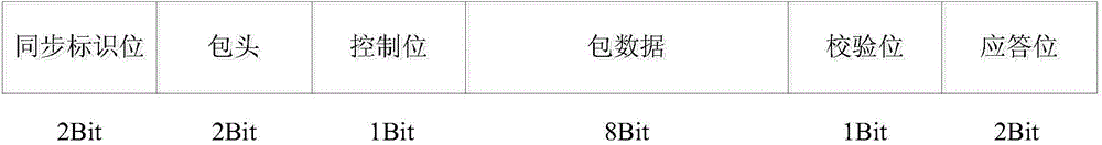
[0039] The implementation of the CBUS bus data detection focuses o...


PUM


Abstract

The invention discloses a CBUS data receiving device, which comprises an idle state detection module, a synchronizing pulse detection module, a packet header file detection module, a control bit detection module, a data receiving module, a first checking module, a second checking module, a third checking module and an answering module. The invention also discloses a CBUS data receiving method. The device and the method conform to a sending specification of the CUBS in an MHL (Mobile High-Definition Link) protocol, and can receive a data packet sent by a sender. When the received data packet has a link layer check bit error, the data packet can be abandoned, and the system can return to the idle state. The device and the method have the advantages that the check bit error detection can be fast completed by using signal features of the CBUS. Compared with a common method of using hardware logics for calculating and detecting a check bit, the method and the device have the advantages that a great number of hardware resources are saved, and the error detection efficiency is improved.

Description

technical field [0001] The invention relates to a CBUS (Link Control Bus) bus data receiving device. The invention also relates to a CBUS bus data receiving method. Background technique [0002] With the widespread use and further development of smart phones and high-definition televisions, it has become a mainstream trend to share information such as videos or pictures in mobile phones with high-definition televisions in real time. The MHL (Mobile High-Definition Link, mobile terminal high-definition video standard interface) interface solves the user's demand for connecting smart phones to high-definition TVs. [0003] The MHL interface includes five signals: MHL+, MHL-, CBUS, VBUS, and GND. Among them, MHL+ and MHL- are a pair of differential signals to complete the audio and video data transmission function; VBUS signal is a power signal, GND is a ground signal, and CBUS signal is a set of DDC (Direct Digital Control) channel and MHL sideband channel signal Based on o...

Claims


Application Information

Patent Timeline
Patent Type & Authority Applications(China)
IPC IPC(8): G06F13/38G06F13/42
Inventor 刘晓燕
Owner SHANGHAI HUAHONG INTEGRATED CIRCUIT
Why Eureka
Try Eureka