Service transmission method and apparatus

A business and service layer technology, applied in the field of communication, can solve the problems of large logic resource occupation and high complexity of hardware implementation, and achieve the effects of avoiding the conversion process, improving bandwidth utilization, and saving logic resources

Inactive Publication Date: 2017-08-11
ZTE CORP
View PDF0 Cites 9 Cited by
  • Summary
  • Abstract
  • Description
  • Claims
  • Application Information

AI Technical Summary

Problems solved by technology

[0004] The technical problem to be solved by the present invention is to provide a method and device for service transmission to solve the problem of mutual conversion between space division multiplexing and time division multiplexing in service transmission, as well as the problems of large logic resource occupation and high complexity of hardware implementation

Method used


Image

  • Service transmission method and apparatus
  • Service transmission method and apparatus
  • Service transmission method and apparatus

Examples


specific Embodiment 1

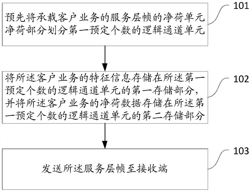
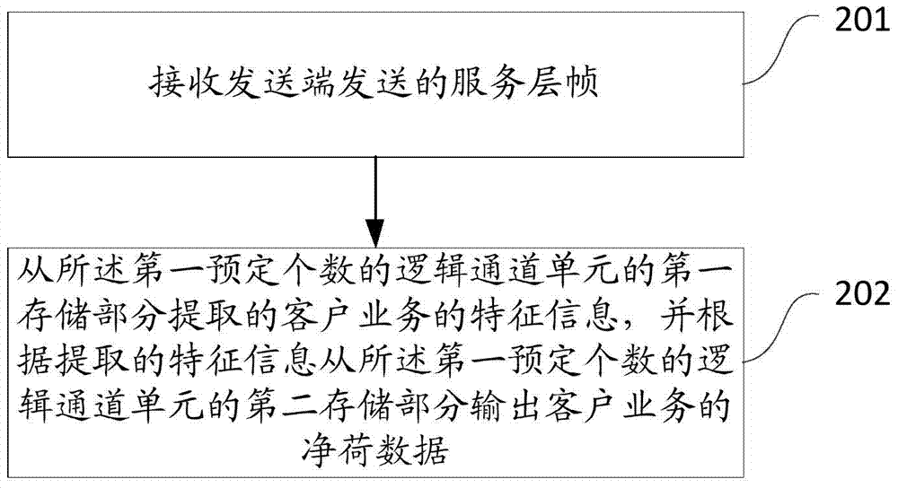
[0174] Attached below Figure 7 And attached Figure 8 , the service layer frame is a high-order ODU4 frame, and the customer service is an ODU2 service. With 10 ODU2 channels mapped to one ODU4 frame, the specific steps of the service transmission method provided by the present invention are described in detail. It should be noted that, in this implementation example, the size of the logical channel unit used is 476 bytes, and the ODU4 frame includes 32 logical channel units. In addition, this implementation example does not consider the fault-tolerant processing of the overhead, and only provides a a storage structure.

[0175] Step 1.1: See Figure 7 , which shows a schematic diagram of allocation of OPUk overhead bytes in Embodiment 1 of the present invention. Figure 7 In , LCU represents the logical channel unit, LCU overhead represents the first storage part of the logical channel unit, and 476-n byte payload represents the second storage part of the logical channel ...

specific Embodiment 2

[0180] combined with Figure 9 And attached Figure 10 , the service layer frame is a high-order ODU4 frame, the customer service is an ODU1 service, and 40 ODU1 services are mapped to one ODU4 frame, and the specific steps of the service transmission method provided by the present invention are described in detail. It should be noted that, in this implementation example, the size of the logical channel unit used is 544 bytes, and the ODU4 frame includes 28 logical channel units. In addition, this implementation example does not consider the fault-tolerant processing of the overhead, and only provides A storage structure.

[0181] Step 2.1: See Figure 9 , which shows a schematic diagram of allocation of OPUk overhead bytes in Embodiment 2 of the present invention. Figure 9 In , LCU represents the logical channel unit, LCU overhead represents the first storage part of the logical channel unit, and 544-n byte payload represents the second storage part of the logical channel...


PUM


Abstract

The invention provides a service transmission method and apparatus. The service transmission method is applied to a sending end and comprises the following steps: dividing a payload part of a payload unit bearing a service layer frame of client service into a first predetermined number of logic channel units in advance, wherein each logic channel unit comprises a first storage part used for storing the cost of the client service and a second storage part used for storing the payload data of the client service; storing feature information of the client service in the first storage parts of the first predetermined number of logic channel units, and storing the payload data of the client service in the second storage parts of the first predetermined number of logic channel units; and sending the service layer frame to a receiving end. Therefore, all bytes processed within a clock cycle can belong to a certain logic channel unit, thereby avoiding the space division-time division- space division conversion process, saving logic resources, reducing the hardware implementation complexity, reducing the number of occupied bytes, preventing bandwidth waste and improving the bandwidth utilization rate.

Description

technical field [0001] The present invention relates to the technical field of communication, in particular to a method and device for service transmission. Background technique [0002] At present, in the Optical Transport Network (OTN, Optical Transport Network), the most commonly used mapping method for mapping client signals to OTN and low-rate optical channel data unit (ODU, optical channel data unit) to high-rate ODU is the general mapping procedure (GMP , Generic Mapping Procedure). GMP divides the optical channel payload unit (OPU, optical channel payload unit) of the OTN frame into multiple time slots of the same size in a time slot-based manner. In a 100G OTN frame, the size of the time slot is 1.25G, that is, one OPU4 (100G) can be divided into 80 1.25G time slot units, and client signals and low-rate ODUs occupy multiple time slots according to the speed. As the OTN rate continues to increase, the size of the time slot is also changing. In Beyond 100G OTN, the ...

Claims


Application Information

Patent Timeline
Patent Type & Authority Applications(China)
IPC IPC(8): H04B10/25H04B10/50H04J3/16H04Q11/00H04Q11/06
CPCH04B10/2589H04B10/50H04J3/1652H04Q11/0062H04Q11/06
Inventor 张源斌鄢媛媛付锡华
Owner ZTE CORP
Why Eureka
Try Eureka