Multi-objective reactive power optimization method for solving Pareto optimal solution set

An optimization method and multi-objective technology, applied in reactive power compensation, reactive power adjustment/elimination/compensation, etc.

Active Publication Date: 2015-09-09
ELECTRIC POWER RESEARCH INSTITUTE, CHINA SOUTHERN POWER GRID CO LTD +1
View PDF2 Cites 9 Cited by
  • Summary
  • Abstract
  • Description
  • Claims
  • Application Information

AI Technical Summary

Problems solved by technology

The goal programming method predetermines the degree of preference for each objective function, then constructs a single-objective optimization model by adding a priority factor, and then solves a single-objective optimization problem. The disadvantage of this method is that each objective needs to be known in advance order of priority

Method used


Image

  • Multi-objective reactive power optimization method for solving Pareto optimal solution set
  • Multi-objective reactive power optimization method for solving Pareto optimal solution set
  • Multi-objective reactive power optimization method for solving Pareto optimal solution set

Examples


Embodiment Construction

[0094] The present invention will be described in detail below with reference to the accompanying drawings and embodiments.

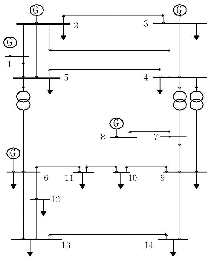
[0095] Taking the IEEE 14-node system as an example, the system has 14 nodes, 17 transmission lines, 3 transformers, 5 generator sets, node 1 as a balance node, and 3 load nodes equipped with capacitive reactive power compensation. The nodes are nodes 9, 13, and 14. The voltage of the PV node and the balance node is set to 0.90-1.10, the voltage of the PQ node is set to 0.95-1.05, and the variable ratio range of the adjustable transformer is 0.90-1.10. And it is assumed that the cost of reactive power compensation for all units is 1 (using per unit value). For the wiring diagram of the IEEE14 node system, see image 3 . The algorithm steps of multi-objective reactive power optimization using the original dual interior point method Pareto optimal solution set are described in detail below:

[0096] The first step is to set the system parameters of th...


PUM


Abstract

The invention discloses a multi-objective reactive power optimization method for solving a Pareto optimal solution set. The method of the invention converts the problem into a problem of solving reactive power optimization containing two objective functions, boundary points of the two objective functions are respectively solved directly in a tangent method, an inequality constraint method is then adopted to solve Pareto frontier formed by the two objective functions, during the calculation process, algorithm for solving a single-objective reactive power optimization model adopts a primal dual interior point method, and a point for an initial value adopts a result of power flow calculation. The multi-objective reactive power optimization method for solving a Pareto optimal solution set has the advantages that optimization of multiple objectives is comprehensively considered during the reactive power optimization process, subjectivity generated when a single objective reactive power optimization model is built by other algorithms can be effectively avoided, the distribution condition of each objective function can be intuitively seen from the Pareto frontier surface, and a reasonable and reliable decision which can meet needs of system operation can be made conveniently by a decision maker.

Description

technical field [0001] The invention relates to a multi-objective reactive power optimization method for solving Pareto optimal solution sets, and belongs to the technical field of electric power. Background technique [0002] At present, the reactive power optimization problem of the power system is to minimize the system network loss and reactive power compensation cost of the power system under the condition of ensuring the power quality. Therefore, it itself is a multi-objective optimization problem. [0003] At present, there is no unified method for solving multi-objective optimization. Traditional multi-objective optimization processing methods mainly include ideal point method, efficacy coefficient weighting method, objective programming method, sequence optimization method, Pareto optimal solution set method (with constraints) and other methods . The ideal point method is to first solve the optimal objective value of the optimization problem under each single objec...

Claims


Application Information

Patent Timeline
Patent Type & Authority Applications(China)
IPC IPC(8): H02J3/18
CPCY02E40/30
Inventor 金小明陈皓勇李蓉蓉杨柳卢斯煜张聪
Owner ELECTRIC POWER RESEARCH INSTITUTE, CHINA SOUTHERN POWER GRID CO LTD
Why Eureka
Try Eureka