
Driving circuit of LED (light-emitting diode) lamp as well as lighting equipment

A technology of LED lights and driving circuits, which is applied in the field of lighting, can solve the problems of large size of the driving circuit module, large size, technical lag, etc., and achieve the effect of improving user acceptance, simple overall circuit, and easy promotion and application

Inactive Publication Date: 2015-09-09
SHANGHAI DANGOO ELECTRONICS TARDING
View PDF6 Cites 1 Cited by
  • Summary
  • Abstract
  • Description
  • Claims
  • Application Information

AI Technical Summary

Problems solved by technology

[0003] For example, the appearance of LED filament lamps is similar to ordinary incandescent lamps, which makes the user's acceptance higher. However, due to the relatively lagging technology related to the drive circuit of LED filament lamps, the size of the drive circuit module is relatively large. Therefore, the traditional LED In all filament lamps, it is necessary to set up a plastic shell specially used for placing the drive circuit module at the joint between the lamp cap and the bulb, so that the appearance of the entire LED filament is different to a certain extent, which greatly reduces the acceptance of the user. and not convenient for daily use
[0004] In addition, currently, in order to make LED filament lamps realize SCR dimming like incandescent lamps, it is generally necessary to install a dimmable switch power circuit module, but due to the large size of the power circuit module, it cannot be directly placed in the LED filament lamp. In the lamp holder, the overall volume of the LED filament lamp is further increased

Method used


Image

  • Driving circuit of LED (light-emitting diode) lamp as well as lighting equipment
  • Driving circuit of LED (light-emitting diode) lamp as well as lighting equipment

Examples


Embodiment 1

[0034] figure 1 It is a schematic diagram of the module structure of the driving circuit of the LED lamp in the embodiment of the present application; figure 1 As shown, an LED lamp drive circuit in this application can be based on a system that uses AC power to supply power to LED lamps, including:

[0035] The AC power supply can be daily civilian AC power (such as domestic civilian AC 220V / 50Hz, of course, other specifications of AC power can also be used, as long as it is within the rectification range of the subsequent rectification module), used to provide LED lights electric energy;

[0036] The rectification module has an AC input terminal and a DC output terminal, and the above-mentioned AC power supply is connected to the AC input terminal, so that the AC power provided by the AC power supply can be rectified into DC power by the rectification module, and output through the DC output terminal;

[0037] The thermistor and the LED light are connected in series at the...

Embodiment 2

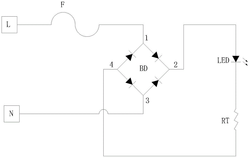
[0044] figure 2 It is the circuit diagram of the driving circuit of the LED lamp in the embodiment of the present application, such as figure 2 As shown, based on the first embodiment above, the driving circuit of the LED lamp in the embodiment of the present application includes:

[0045] An AC power supply (not shown in the figure) with a connection terminal L and a connection terminal N, and the connection terminal L is connected to the AC input terminal 1 of the bridge rectifier BD through a fuse F, and the connection terminal N is connected to the bridge rectifier BD The AC input terminal 3 enables the bridge rectifier BD to rectify the AC power provided by the AC power supply and output DC power through the DC output terminal 2 and the DC output terminal 4 .

[0046] Further, the above-mentioned driving circuit also includes an LED filament lamp and a thermistor RT connected in series between the above-mentioned DC output terminal 2 and the DC output terminal 4, that ...


PUM


Abstract

The invention provides a driving circuit of an LED (light-emitting diode) lamp as well as lighting equipment, and relates to the technical field of lighting. A thermistor is linked in series between the LED lamp and a power supply, so that the current flowing through the LED lamp is enabled to be within the rated power range, thereby further realizing the constant current effect of the LED lamp, moreover, a silicon controlled light modulator can also be connected in series to adjust the brightness of the LED lamp; in addition, the whole circuit is simple, easy to realize, small in size, and capable of being wholly embedded into the lamp holder of the LED lamp, so that the overall appearance of the LED lamp is similar to that of an incandescent lamp, the user acceptance is effectively improved, and the popularization and application are facilitated.

Description

technical field [0001] The invention relates to the technical field of lighting, in particular to a driving circuit of an LED lamp and lighting equipment. Background technique [0002] At present, LED, as a new generation of point light source, is widely used in people's daily life due to its advantages of high electro-optic conversion rate, long life, low cost and environmental protection, which leads to the rapid development of LED technology and derives Wide variety of lighting equipment. [0003] For example, the appearance of LED filament lamps is similar to ordinary incandescent lamps, which makes the user's acceptance higher. However, due to the relatively lagging technology related to the drive circuit of LED filament lamps, the size of the drive circuit module is relatively large. Therefore, the traditional LED In all filament lamps, it is necessary to set up a plastic shell specially used for placing the drive circuit module at the joint between the lamp cap and t...

Claims


Application Information

Patent Timeline
Patent Type & Authority Applications(China)
IPC IPC(8): H05B37/02
CPCF21V23/00F21V23/02
Inventor 朱明星
Owner SHANGHAI DANGOO ELECTRONICS TARDING
Learn More