Home appliance fault monitoring equipment
A technology for fault monitoring and household appliances, which is applied in the field of circuits, and can solve problems such as failures, affecting the use of household appliances, and troublesome monitoring of household appliances.
- Summary
- Abstract
- Description
- Claims
- Application Information
AI Technical Summary
Problems solved by technology
Method used
Image
Examples
Embodiment 1
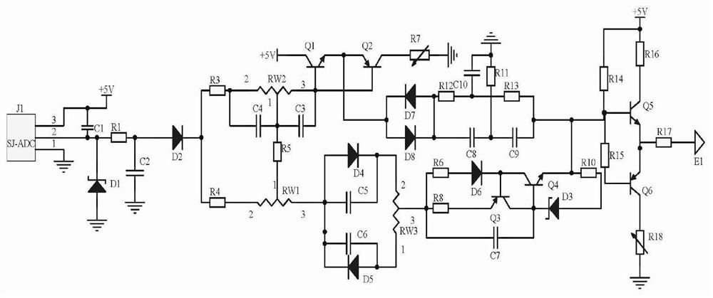
[0014] EXAMPLES, household appliance fault monitoring equipment, including frequency acquisition circuitry, separation calibration circuit, and signal output circuit, said frequency acquisition circuit acquisition of a signal transmission channel input in a home electrical fault monitoring device control terminal, the signal transmission channel is The control terminal receives the channel of the analog signal in the household appliance fault monitoring device, the separation calibration circuit, using variable resistors RW1, variable resistor RW2, and capacitance C4, and the capacitor C3 constitutes a separation circuit to divide the signal into two signals different from different amplitude. , All the way using the triode Q1, the triode Q2 constitutes a push-pull circuit to reduce the signal of the signal, and the capacitor C8-capacitor C10 and the resistor R13 constitute a single frequency signal output circuit after the signal output circuit, two The road uses variable resisto...
Embodiment 2
[0017]Embodiment 2 Based on the example one, the signal output circuit uses the triode Q5, the triode Q6, and the resistor R14, and the resistor R15 constitutes a composite circuit to prevent signal distortion, further ensuring the reliability of the transmission of the signal, and transmits the signal transmitter E1. Sending to the alarm module in the alarm module in the alarm module in the alarm module, the base electrode electrical resistance R14, the generation of the triode Q5 and the emitter of the transmitter of the triode Q4, and the electrical resistance R14, and the resistor R16 of the electrical resistance R16, the resistor R16. One end of the power supply + 5V, the emitter of the emitter of the triode Q5, and one end of the emitter Q6 of the triode Q6, and the other end of the triode Q6, the other end of the triode Q6, the collector of the triode Q6, and the end of the variable resistor R18, variable The other end of the resistor R18 is grounded, and the other end of t...
Embodiment 3
[0018] Example 3. On the basis of the second embodiment, the frequency acquisition circuit 1 selects the signal frequency collector J1 acquired by the SJ-ADC collector J1 to collect the signal transmission channel input terminal in the control terminal, when the home appliance At the time of the fault, even if the home appliance is not used, it is in standby state. At this time, the signal frequency is abnormally, the signal frequency collector J1 outputs a high level signal, which can trigger the alarm module in the home appliance fault monitoring device, in turn, the household appliance fault monitoring device The alarm module does not work, the power supply terminal of the signal frequency collector J1 and the power supply C1 are connected to the power supply + 5V, the signal frequency collector J1 is grounded, and the output terminal of the signal frequency collector J1 receives the other end and resistance R1 of the capacitor C1. One end, the negative electrode of the regulat...
PUM
 Abstract
Description
Claims
Application Information
 - R&D
- Intellectual Property
- Life Sciences
- Materials
- Tech Scout
- Unparalleled Data Quality
- Higher Quality Content
- 60% Fewer Hallucinations
Browse by: Latest US Patents, China's latest patents, Technical Efficacy Thesaurus, Application Domain, Technology Topic, Popular Technical Reports.
© 2025 PatSnap. All rights reserved.Legal|Privacy policy|Modern Slavery Act Transparency Statement|Sitemap|About US| Contact US: help@patsnap.com


