Fireproof ceramic bottom

A technology of refractory ceramics and bases, applied in the field of refractory ceramics bases, can solve the problems of complex and expensive refractory linings, achieve the effects of simple laying, increased service time, and reduced errors

Active Publication Date: 2015-09-09
REFRACTORY INTELLECTUAL PRORERTY GMBH & CO KG
View PDF4 Cites 2 Cited by
  • Summary
  • Abstract
  • Description
  • Claims
  • Application Information

AI Technical Summary

Problems solved by technology

Refractory lining of the base b

Method used


Image

  • Fireproof ceramic bottom
  • Fireproof ceramic bottom
  • Fireproof ceramic bottom

Examples


Embodiment Construction

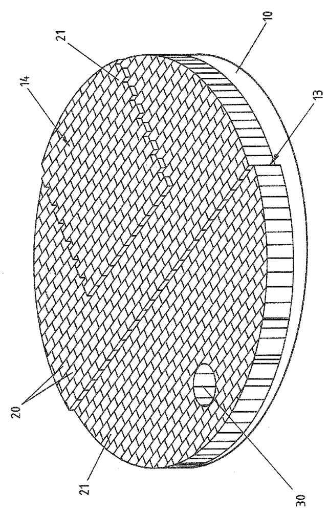
[0078] Figure 1 shows a base with two layers, namely a lower layer 10 and an upper layer 20 arranged on top. Both of them are approximately circular in top view (plan view).

[0079] The lower layer 10 is designed as a permanent lining and is made of a refractory ceramic mass based on alumina. The permanent lining 10 is entirely designed as a prefabricated element and features a horizontal lower surface 10u and a three-dimensionally designed upper surface 10o. Surface 10o is characterized by the following regions:

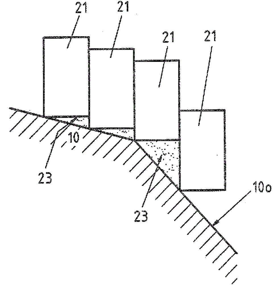
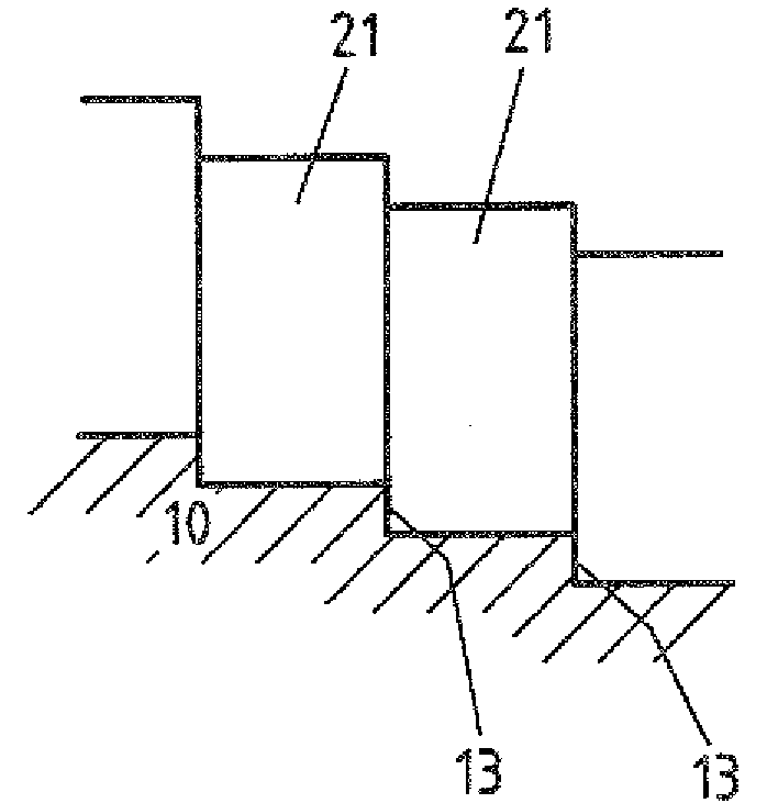
[0080] - about the first rung 13 in the center;

[0081] - raised impact pad 14 in the upper left third;

[0082] All areas of the surface 10 o are inclined at approximately 3° relative to the horizontal, with a slope in the direction towards the discharge area 30 .

[0083] The upper layer 20 , so the wear layer, consists mainly of (>80M.-%) cubic refractory bricks 21 of the same size and uniform layout (except in the area of ​​the discharge opening 30 ).

[...


PUM


Abstract

The floor has a base that includes a lower layer of a refractory ceramic outer lining and a top layer of a refractory ceramic wearing lining (20). The outer lining has an upper surface (20o) with a three-dimensional design which is partially inclined to a horizontal by more than one adjacent to the wearing lining. The wearing lining consists of a refractory ceramic solid brick (21). The outer lining and the wearing lining include an interruption for forming a common outlet for a high-temperature melt.

Description

technical field [0001] The invention relates to a refractory ceramic base (bottom) in the region of the connection to at least one wall of a vessel for handling a high-temperature melt. Background technique [0002] The container may be, for example, a metallurgical bucket. This application is used below to further describe the prior art and the present invention. [0003] Such a bucket is shown eg in US 5.879.616 A. Very simply put, the scoop consists of a base and a wall extending upwards from the base, the scoop having an almost circular internal cross-section so that overall a tank shape results. At least one hole (drain area) is arranged in the base. [0004] The molten metal carried in the bucket enters a downstream device, such as a tundish, through a discharge port (tap). In order to adjust / control the amount of molten metal, there are for example stoppers or sliding plate valves, which are also called control devices. [0005] If slag also gets into the tundish...

Claims


Application Information

Patent Timeline
IPC IPC(8): B22D41/02B22D41/08
CPCB22D41/02B22D41/08F27D1/0003F27D1/0043
Inventor A.马拉尼奇M.赫克M.基尔申
Owner REFRACTORY INTELLECTUAL PRORERTY GMBH & CO KG
Why Eureka
Try Eureka