Pressure die used for dust-free drawing aluminum-coated steel

A pressure mold and pressure mold technology, applied in the field of pressure molds for dust-free drawing of aluminum-clad steel, can solve the problems of enlargement, waste of manpower and material resources, etc., and achieve the effects of prolonging the life of the mold, saving costs, and reducing costs

Active Publication Date: 2015-09-16
常州特发华银电线电缆有限公司
7 Cites 2 Cited by

AI-Extracted Technical Summary

Problems solved by technology

In order to ensure that the liquid does not leak, the pressing force is appropriately increased when the drawing die and the pressure die are installed, so plastic deformation occurs at the contact part between the pressure die and the drawing die. At this time, the cladding rod often breaks when the aluminum-clad steel is drawn, and ...

Method used

[0019] The bore diameter of the transition joint 2 is 0.10-0.20mm larger than the pressure mold 4 bore diameter. The inner hole passing through the transition joint 2 is a little larger than the inner hole size of the normal pressure die 4, so even if a little deformation occurs under a large pressing force, it will not affect the normal drawing ...

Abstract

The invention relates to the aluminum-coated steel technology field, and especially relates to a pressure die used for dust-free drawing aluminum-coated steel. The pressure die used for dust-free drawing aluminum-coated steel comprises a wire drawing die and a pressure die. Hard alloy is arranged at two ends inside the pressure die. The wire drawing die and the pressure die are connected through a transition joint. The transition joint and the pressure die are fixed in a retainer. Inner holes are arranged inside the wire drawing die, the transition joint and the pressure die. The pressure die used for dust-free drawing aluminum-coated steel can meet gap requirements needed by dust-free drawing aluminum-coated steel, and installation of the structure can be finished for one time, a phenomenon that the transition joint inclines and aluminum-coated steel drawing is affected cannot be generated. The inner hole of the transition joint is slightly larger than an inner hole of a common pressure die in size, and even if a little of deformation is generated under action of a large compacting force, normal drawing of aluminum-coated steel cannot be affected. The service life of the die is prolonged, even if deformation of the transition joint is large, replacing of one joint is only needed, and the investment cost is saved.

Application Domain

Technology Topic

AluminiumDeep drawing +4

Image

  • Pressure die used for dust-free drawing aluminum-coated steel
  • Pressure die used for dust-free drawing aluminum-coated steel
  • Pressure die used for dust-free drawing aluminum-coated steel

Examples

  • Experimental program(1)

Example Embodiment

[0021] Example
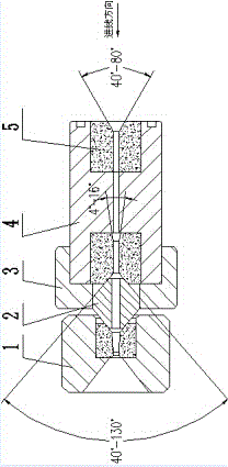
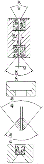
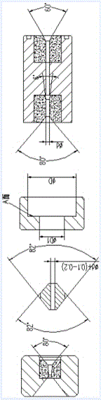
[0022] Such as Figure 4 As shown, the pressure die 4 is cylindrical, and the two ends of the pressure die 4 are equipped with cemented carbide 5. The angle of the inner hole of the cemented carbide 5 at one end in the line direction is 60o, and the other end of the cemented carbide 5 The angle of the inlet direction is 6o, and the angle of the outlet direction of the cemented carbide 5 at the other end is 80°. A transition joint 2 is installed between the cylindrical pressure die 4 and the wire drawing die 1. The transition joint 2 is olive-shaped. In order to ensure a firm connection between the transition joint and the wire drawing die, and the lubricating medium does not leak, the transition joint 2 is The taper is set to 82o. The inner hole diameter of the transition joint 2 is 0.10-0.20mm larger than the inner hole diameter of the pressure die 4. In order to ensure the coaxiality of the transition joint and the pressure die and the drawing die during the overall installation to ensure the smooth drawing, a cage is installed on the pressure die and the transition joint. The gap between the small hole D1 on the cage 3 and the outer circle of the transition joint 2 is 0.05-0.08mm, the gap between the large hole D and the outer circle of the pressure die 4 is also 0.05-0.08mm, and the small hole D1 of the cage 3 The coaxiality between the large hole D and the large hole D is required to be 0.015mm, and the perpendicularity between the A surface and the large hole D is 0.02mm. After testing, the cage with this size requirement can meet the production requirements.
[0023] Installation method:
[0024] The pressure die 4 is firmly installed on the holder 3, and then the transition joint 2 is placed in the holder 3 to ensure that the transition joint 2 is not deflected. Connect the connected pressure die 4, the cage 3, and the transition joint 2 to the wire drawing die 1, and install a large pressing force to compress them.
[0025] This kind of pressure die for dust-free drawing aluminum-clad steel can ensure the clearance required for dust-free drawing of aluminum-clad steel. The installation of the structure can be in place at one time and will not produce transition joints that affect the drawing of aluminum-clad steel. Phenomenon: The inner hole of the transition joint is a bit larger than the inner hole of the normal pressure die, so even a little deformation under a large compression force will not affect the normal drawing of aluminum clad steel, and the life of the die is extended, even if the transition joint is deformed If it is too large, only one connector needs to be replaced, which has a low cost and can save a lot of costs.

PUM

PropertyMeasurementUnit
Diameter0.1 ~ 0.2mm
tensileMPa
Particle sizePa
strength10

Description & Claims & Application Information

We can also present the details of the Description, Claims and Application information to help users get a comprehensive understanding of the technical details of the patent, such as background art, summary of invention, brief description of drawings, description of embodiments, and other original content. On the other hand, users can also determine the specific scope of protection of the technology through the list of claims; as well as understand the changes in the life cycle of the technology with the presentation of the patent timeline. Login to view more.

Similar technology patents

Wear-resistant mold surface nanocrystal coating and preparation method thereof

InactiveCN111893421AImprove mold lifeHigh quality surface finishMolten spray coatingSurface smoothnessCoating
Owner:常熟市绿一电器配件制造有限公司

Precise hot forming method for deep-cavity ribbed notched irregular cylindrical forge piece

ActiveCN113996743AReduce forming loadImprove mold lifeMetal-working apparatusEngineeringHeat treating
Owner:HARBIN INST OF TECH +1

Punching machine for machining piston assemblies used for automobile brakes

ActiveCN105234331AImprove mold strengthImprove mold lifeForging/hammering/pressing machinesForging press detailsPistonEngineering
Owner:浙江铭锐金属制品股份有限公司

Golf ball mold and golf ball manufacturing method

ActiveUS20130154156A1Minimizing abrasionImprove mold lifeTailstocks/centresConfectioneryBiomedical engineeringContamination
Owner:BRIDGESTONE SPORTS

Classification and recommendation of technical efficacy words

  • Low cost
  • Improve mold life

Semiconductor device

InactiveUS6975142B2Low costReduce manufacturing stepsTransistorSolid-state devicesVoltage amplitudeSemiconductor
Owner:SEMICON ENERGY LAB CO LTD

Special die for stamping inward bending part and stamping method

ActiveCN104475579AHigh fillet strengthImprove mold lifeShaping toolsEngineeringMechanical engineering
Owner:山东省未来人才科技有限公司

Heat treatment technology for die Cr12MoV steel

InactiveCN107723434AImprove mold lifeQuenchingTool steel
Owner:HENGYANG FENGSHUN AXLE CO LTD
Why Eureka
Try Eureka