Wheel bearing device and manufacturing method therefor

a technology of a bearing device and a manufacturing method, which is applied in the direction of bearing unit rigid support, transportation and packaging, mechanical equipment, etc., can solve the problems of increasing manufacturing costs, and achieve the effects of preventing the concentration of material flow pressure, preventing early fracture, and improving the life of the di

Active Publication Date: 2013-08-20
JTEKT CORP
View PDF31 Cites 4 Cited by
  • Summary
  • Abstract
  • Description
  • Claims
  • Application Information

AI Technical Summary

Benefits of technology

[0013]With the above configuration, the plurality of flange portions are formed radially on the outer peripheral surface located between the shaft portion and the fitting shaft portion by cold side extrusion. Thus, it is possible to reduce manufacturing costs while reducing the weight.
[0015]Therefore, it is possible to prevent concentration of material flow pressure on the edge portion of the cross-sectional shape of each flange molding portion of the molding die.
[0016]As a result, it is possible to improve the die life by preventing early fracture due to concentration of stress on the edge portion of the cross-sectional shape of each flange molding portion of the molding die and, by extension, it is possible to reduce manufacturing costs of the wheel bearing device.
[0018]With the above configuration, it is possible to easily manufacture the wheel bearing device, and it is possible to reduce manufacturing costs of the wheel bearing device by improving the die life of the forging die apparatus.

Problems solved by technology

However, in the existing wheel bearing device, after a forging is manufactured by cold forging, a plurality of flange portions formed of raised pieces need to be formed at one shaft end portion of the forging, so manufacturing costs increase.

Method used


Image

  • Wheel bearing device and manufacturing method therefor
  • Wheel bearing device and manufacturing method therefor
  • Wheel bearing device and manufacturing method therefor

Examples


first embodiment

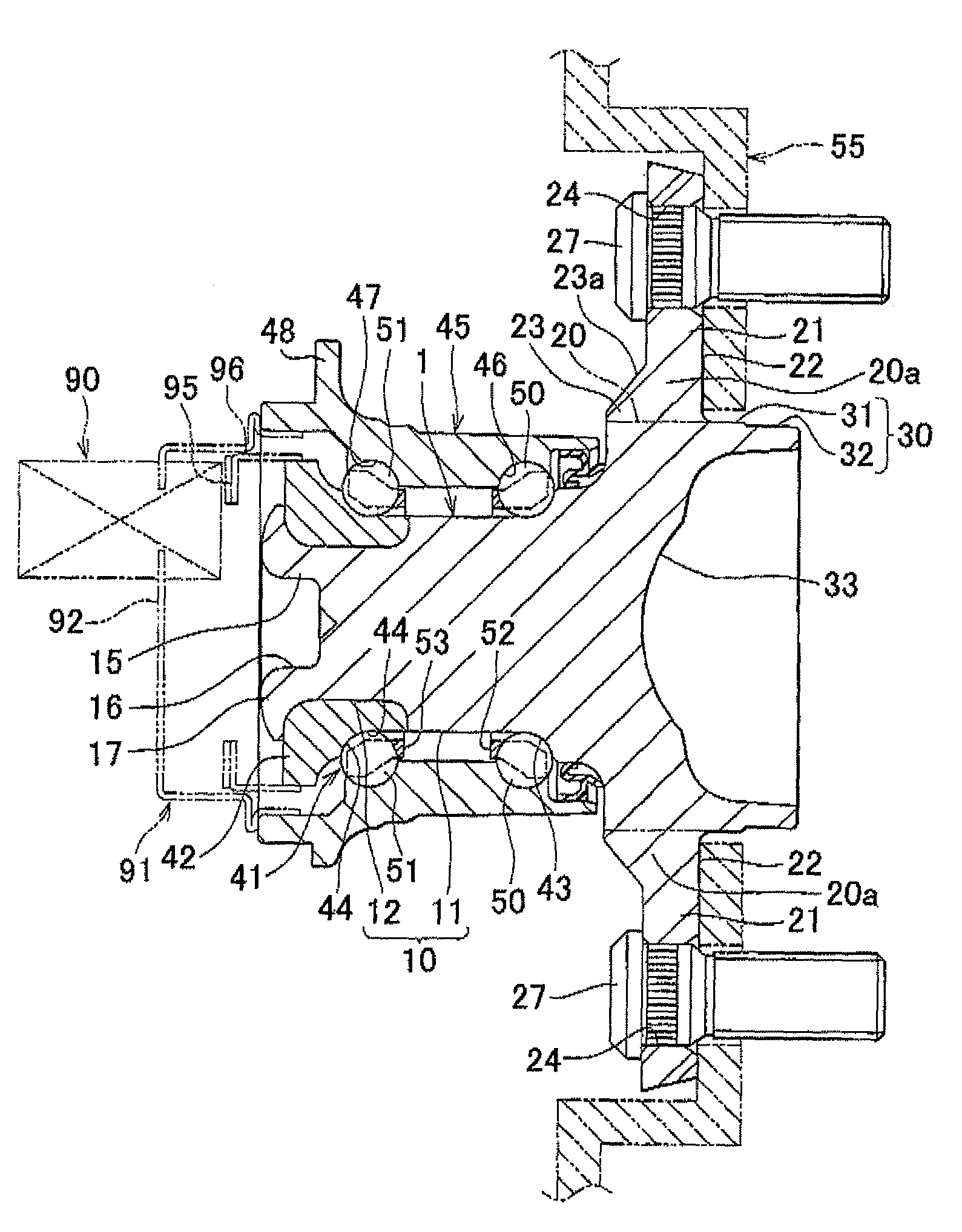
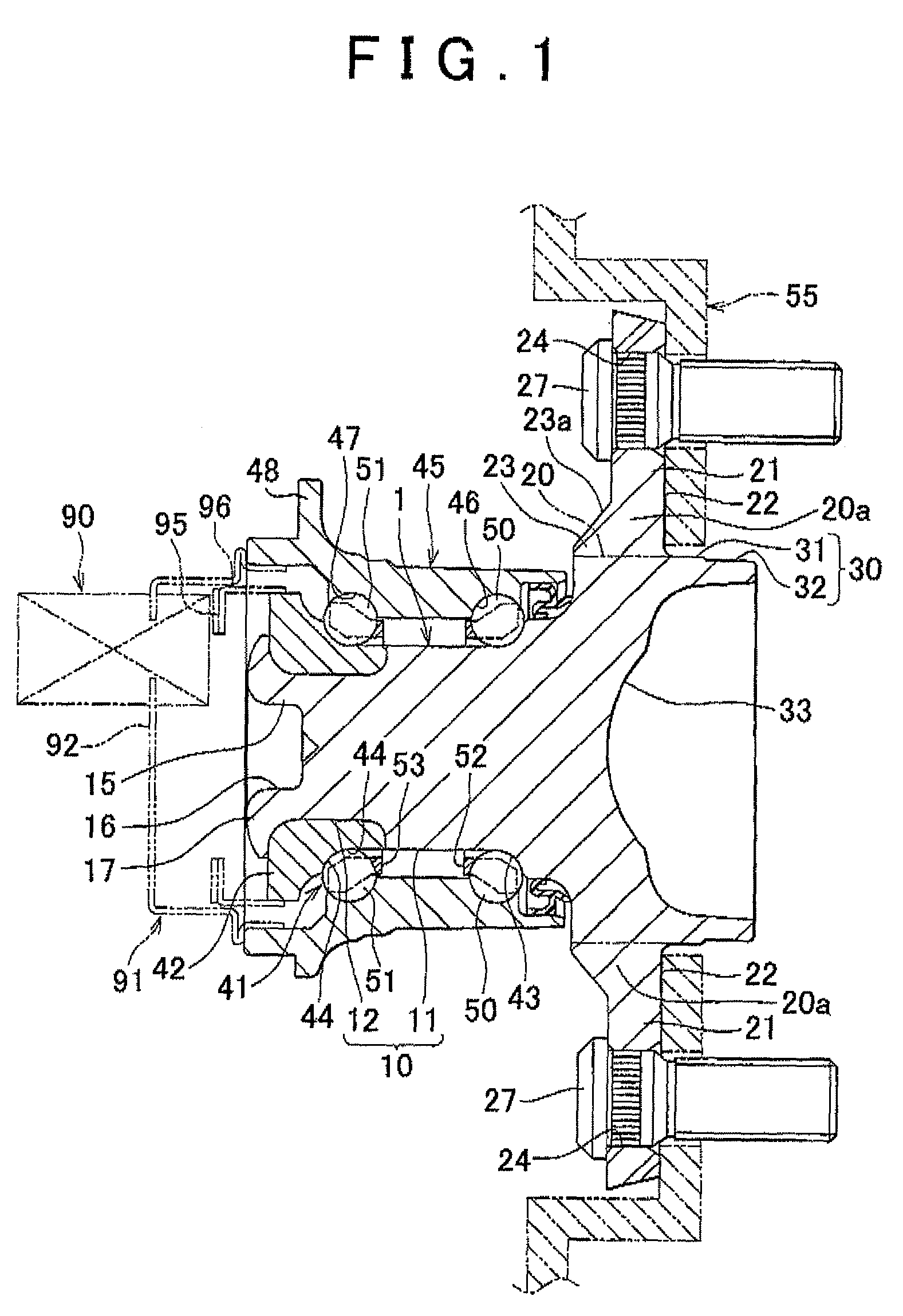
[0043]First, a wheel bearing device according to a first embodiment of the invention will be described with reference to FIG. 1 to FIG. 3.

[0044]As shown in FIG. 1, a wheel hub unit includes a unit of a flanged shaft member (hub wheel) 1 and a double row angular contact ball bearing 41. The wheel hub unit serves as the wheel bearing device. The double row angular contact ball bearing 41 serves as a rolling bearing.

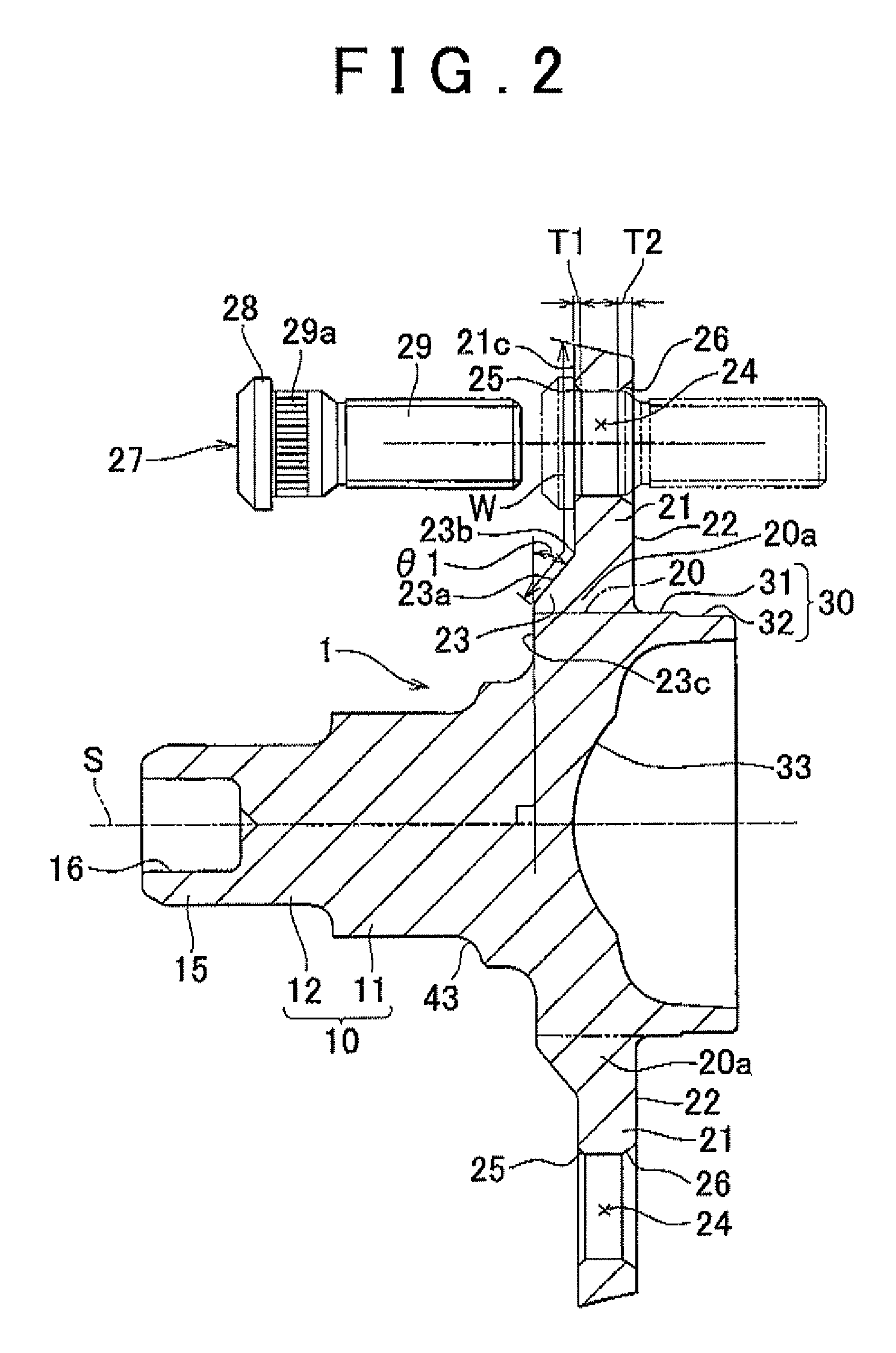
[0045]The flanged shaft member 1 integrally includes a shaft portion 10, a fitting shaft portion 30, a flange proximal portion 20a and a plurality of flange portions 21. The double row angular contact ball bearing 41, which serves as the rolling bearing, is assembled onto the outer peripheral surface of the shaft portion 10. The fitting shaft portion 30 is formed on one end side of the shaft portion 10 and has a larger diameter than that of the shaft portion 10. The fitting shaft portion 30 is fitted to a center hole of a wheel (not shown). The flange proximal portion 20a i...

second embodiment

[0098]Next, a wheel bearing device according to a second embodiment of the invention will be described with reference to FIG. 10 and FIG. 11.

[0099]As shown in FIG. 10, in the second embodiment as well, a plurality of flange portions 121 of a flanged shaft member 101 are formed by side extrusion when a forged recess 133 is formed at the center of the end surface of a fitting shaft portion 130 by cold forging.

[0100]As shown in FIG. 11, in the second embodiment, each flange portion 121 is formed so that both side portions 121g are thinner than a widthwise center portion 121f in the cross-sectional shape taken perpendicularly to the longitudinal direction. In addition, edge portions 121e of the cross-sectional shape of each flange portion 121 are formed in an R-chamfered shape.

[0101]The other configuration of the second embodiment is similar to that of the first embodiment, so the description thereof may be omitted where appropriate. This also applies to the embodiments described later....

third embodiment

[0111]Next, a wheel bearing device according to a third embodiment of the invention will be described with reference to FIG. 13 and FIG. 14.

[0112]As shown in FIG. 13, a seal sliding portion 57 is molded by cold forging with predetermined accuracy. In addition, the seal sliding portion 57 is formed of a bonderlube-treated film or a molybdenum disulfide film so that the coefficient of friction of the surface is low.

[0113]In addition, the characteristic of the area of the flange portions 21 and the flange proximal portion 20a in the third embodiment as viewed in the axial direction will be described. The shaded portion in FIG. 14 indicates a region in which the first molding die 71 contacts the second molding die 72 within a region of an outside diameter circle to which the flange portions 21 are extended in the secondary molding of cold forging. In other words, the shaded portion is a portion, by which the flange portions 21 are lightened.

[0114]Here, where the outside diameter of each...


PUM

PropertyMeasurementUnit
thicknessaaaaaaaaaa
thicknessaaaaaaaaaa
radiusaaaaaaaaaa

Abstract

A wheel bearing device of the invention includes a flanged shaft member that includes a shaft portion to which a rolling bearing is assembled, a fitting shaft portion that is formed on one end side of the shaft portion and that is fitted to a center hole of a wheel, and a plurality of flange portions that extend radially outward on an outer peripheral surface located between the shaft portion and the fitting shaft portion and each of which has a through bolt hole in which a hub bolt for fastening the wheel is arranged. Each flange portion of the wheel bearing device is formed by side extrusion when a forged recess is formed at a center of an end surface of the fitting shaft portion by cold forging. An edge portion of a cross-sectional shape taken perpendicularly to a longitudinal direction of each flange portion is formed in an R-chamfered shape.

Description

INCORPORATION BY REFERENCE[0001]The disclosure of Japanese Patent Applications No. 2009-034583 filed on Feb. 17, 2009, No. 2009-034603 filed on Feb. 17, 2009, No. 2009-034604 filed on Feb. 17, 2009, No, 2009-034605 filed on Feb. 17, 2009 and No. 2010-27676 filed on Feb. 10, 2010 including the specifications, drawings and abstracts are incorporated herein by reference in its entirety.BACKGROUND OF THE INVENTION[0002]1. Field of the Invention[0003]The invention relates to a wheel bearing device and a manufacturing method therefor.[0004]2. Description of the Related Art[0005]There is a wheel bearing device that includes a flanged shaft member (which may also be called hub wheel). The flanged shaft member has a shaft portion, a fitting shaft portion and a plurality of flange portions. A rolling bearing is assembled to the shaft portion. The fitting shaft portion is formed on one end of the shaft portion, and has a larger diameter than that of the shaft portion. A center hole of a wheel ...

Claims


Application Information

Patent Timeline
Patent Type & Authority Patents(United States)
IPC IPC(8): F16C13/00B21D22/00
CPCB21K1/12B21K1/40F16C33/64B60B27/00F16C2326/02
Inventor MASUDA, YOSHINORIYOKOTA, TATSUYANAKAO, MOTONORI
Owner JTEKT CORP
Why Eureka
Try Eureka