Synchronous element

A technology of synchronous components and synchronous rings, which is applied in the direction of clutches, mechanically driven clutches, mechanical equipment, etc., can solve problems such as vibration, unreliable avoidance of synchronous rings, and uneven operation of three-cylinder engines than four-cylinder engines, etc., to achieve a compact structure , the effect of small construction space

Inactive Publication Date: 2015-09-16
HOERBIGER ANTRIEBSTECHN HLDG
View PDF6 Cites 2 Cited by
  • Summary
  • Abstract
  • Description
  • Claims
  • Application Information

AI Technical Summary

Problems solved by technology

[0004] Since the synchronizing ring has to be adjusted relative to the hub not only in the axial direction but also in the circumferential direction according to the function, it cannot be reliably avoided that the synchronizing ring moves relative to the hub and relative to the sliding sleeve and thereby causes vibrations
Such vibrations even lead to internal loading of the synchronizing ring and can also lead to an uncontrolled impact of the synchronizing ring on the components surrounding the synchronizing ring in the transmission, and can further lead to vibrations in this case
In addition, vibrations can be caused by uneven running of the drive shaft, which will be amplified by the tendency for internal combustion engines used in motor vehicles to have fewer and fewer cylinders; three-cylinder engines run more unevenly than four-cylinder engines

Method used


Image

  • Synchronous element
  • Synchronous element
  • Synchronous element

Examples


Embodiment Construction

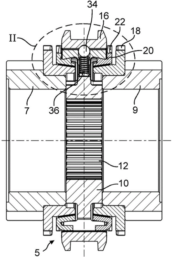
[0035] The drawing shows a synchronizing assembly 5 which is used to connect the two drive gears 7 , 9 , shown schematically here, in a rotationally fixed manner to a drive shaft (not shown). Here, for the sake of simplicity, the transmission gears 7 , 9 are shown with the same diameter; in practice they have different diameters. It is of course also possible to assign only a single gear and thus a single transmission gear to the synchronization assembly.

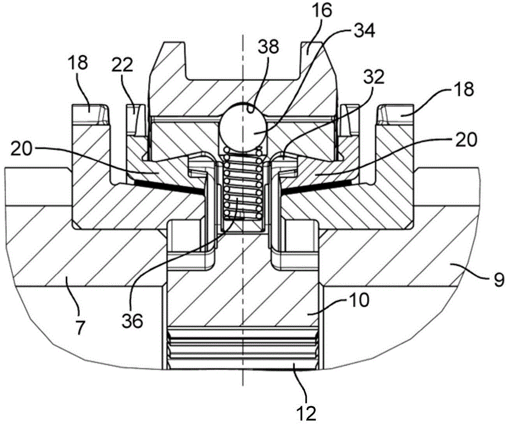
[0036] The synchronizing unit 5 comprises a hub 10 (also referred to as synchronizing body), which is arranged on the drive shaft in a rotationally fixed manner by means of a hub toothing 12 . The drive shaft extends along a center axis M which is at the same time the center axis and the axis of rotation for the drive gears 7 , 9 and the synchronizing assembly 5 .

[0037] The transmission gears 7, 9 are arranged on the transmission shaft as idler gears. When one of the gears is to be used, which is associated with the re...


PUM


Abstract

The present invention relates to a synchronous element, comprising a hub (10), at least one pressure part (30) supported at the hub (10), and at least one synchronous loop (20), wherein the pressure part (30) is provided with a centring surface (40) directly attached at an attachment surface (50) configured at the synchronous loop (20).

Description

technical field [0001] The invention relates to a synchronizing assembly having a hub, at least one pressure part and at least one synchronizing ring. The invention relates in particular to a synchronization assembly for use in a synchronization system of the "BorgWarner" type. Background technique [0002] In a BorgWarner synchronization system, a hub (also referred to as a synchronization body) is arranged in a rotationally fixed manner on a shaft of a transmission, which is used, for example, in motor vehicles. Arranged on the hub in a rotationally fixed manner, but displaceable in the axial direction, is a sliding sleeve for producing a rotationally fixed connection with a drive gear mounted rotatably on both sides of the hub on the drive shaft superior. For this purpose, the gear is provided with a shift toothing, onto which the edge section of the sliding sleeve can be pushed. [0003] Before the sliding sleeve engages in the switching toothing, the revolutions of t...

Claims


Application Information

Patent Timeline
Patent Type & Authority Applications(China)
IPC IPC(8): F16D23/06
CPCF16D23/06F16D2023/0618
Inventor A·戴姆福勒P·明克维茨J·宾德W·沃克O·巴克P·艾希特
Owner HOERBIGER ANTRIEBSTECHN HLDG
Why Eureka
Try Eureka