Disc valve with mechanical linkage of main and auxiliary valves

A disc valve, mechanical technology, applied in mechanical equipment, valve operation/release device, valve details, etc., can solve the problem of pressure in the valve cavity, the speed of material accumulation in the middle cavity does not allow the purge port, and the valve cannot be opened normally, etc. question

Active Publication Date: 2017-04-26
BEIJING AEROSPACE PETROCHEM TECH & EQUIP ENG CORP LTD
View PDF2 Cites 0 Cited by
  • Summary
  • Abstract
  • Description
  • Claims
  • Application Information

AI Technical Summary

Problems solved by technology

As a new type of valve with unique structure and outstanding advantages, disc valves have been widely used in energy and chemical industries such as polysilicon, organic silicon, and coal chemical industries. However, in many specific working conditions, only existing disc valves are used alone. The use is difficult to meet the requirements. For example, the disc valve often leaves a purge port in the middle cavity to connect with the on-site gas source, but the high frequency of use and the passing dense phase medium cause the accumulating speed of the middle cavity to not allow the purge port. It is only used during parking and maintenance, and the purge must be introduced into the daily valve action; for example, the position of the disc valve is often repeatedly charged and released on both sides of the inlet and outlet due to technological requirements, which is very likely to cause pressure in the valve cavity. In severe cases, the valve will not be able to open normally. At this time, it is necessary to pressurize or release the pressure in the middle cavity to balance the pressure of the valve and ensure normal operation.

Method used


Image

  • Disc valve with mechanical linkage of main and auxiliary valves
  • Disc valve with mechanical linkage of main and auxiliary valves
  • Disc valve with mechanical linkage of main and auxiliary valves

Examples


Embodiment 1

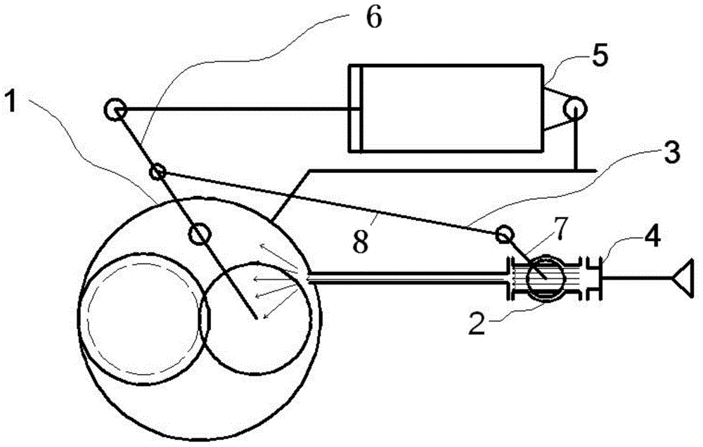
[0022] The disc valve with mechanical linkage of main and auxiliary valves according to the present invention is an eccentric rotary structure, which includes a main valve 1, an auxiliary valve 2, a mechanical linkage system 3, an external gas system 4, etc., the main valve 1 and the auxiliary valve 2 are mechanically connected to each other. The linkage system 3 is connected, the external gas system 4 is connected with the auxiliary valve 2, and the main valve 1 is driven to act by the actuator 5 .

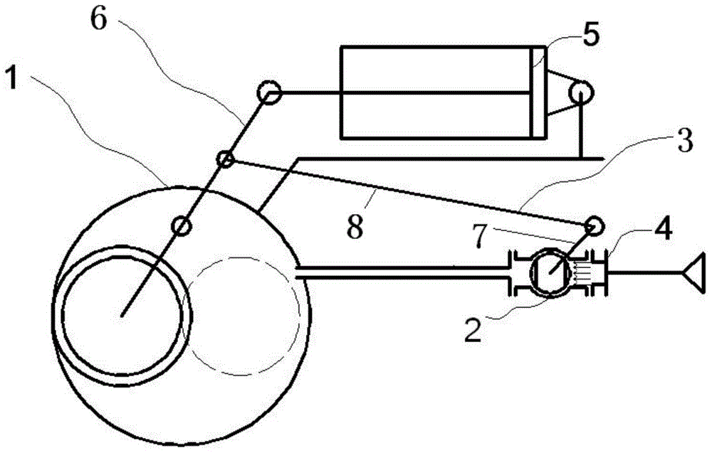
[0023] Such as figure 1 , figure 2 As shown, the main valve 1 is an angular stroke (for example: Patent No. ZL200920163663.X), and the rotation angle of the main valve 1 is 50-70° (for example: 50°, 60° or 70°) for the full stroke. The auxiliary valve 2 is a ball valve, and the rotation angle of the full stroke is 90°.

[0024] Mechanical linkage system 3 is based on the principle of four-bar mechanism, including rod one 7, rod two 8 and rocker arm 6; wherein, one end of rod o...

Embodiment 2

[0030] The disc valve with mechanical linkage of main and auxiliary valves according to the present invention is an eccentric rotary structure, which includes a main valve 1, an auxiliary valve 2, a mechanical linkage system 3, an external gas system 4, etc., the main valve 1 and the auxiliary valve 2 are mechanically connected to each other. The linkage system 3 is connected, the external gas system 4 is connected with the auxiliary valve 2, and the main valve 1 is driven to act by the actuator 5 .

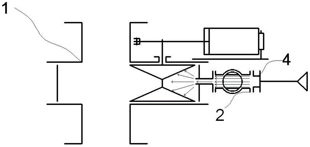
[0031] Such as Figure 5 , 7 As shown, the main valve 1 is a straight-stroke valve (for example: Patent No. US5396919), and the auxiliary valve 2 is also set as a straight-stroke valve.

[0032] The mechanical linkage system 3 is an L-shaped fork structure. The middle of the L-shaped fork structure is set on the fixed point 10. One end of the L-shaped fork structure is connected to the valve stem of the auxiliary valve 2. The L-shaped fork structure There is a slot 9 at the oth...


PUM


Abstract

The invention provides a disc valve with a main valve and an auxiliary valve in mechanical linkage. The disc valve comprises the main valve, the disc valve, a mechanical linkage system and an outer air system. The main valve is connected with the auxiliary valve through the mechanical linkage system, the outer air system is connected with the auxiliary valve, and the main valve is driven to act through an executing mechanism. When the main valve is in angular travel, the rotating angle value of the main valve in the whole travel ranges from 50 degrees to 70 degrees, a ball valve is adopted as the auxiliary valve, the rotating angle of the whole travel of the auxiliary valve is 90 degrees, and the mechanical linkage system is a four-rod mechanism. When the main valve is in the straight travel, the auxiliary valve is also arranged to be a straight travel valve, the mechanical linkage system is an L-shaped shifting fork type structure, and grooves are formed in the mechanical linkage system to be connected with valve rods of the main valve and the auxiliary valve. The disc valve meets the special requirements for the action, sealing, safety, reliability and the like of the valve under special working conditions and other requirements such as main valve pressurizing protection, upstream and downstream gas isolation, pipeline purging, valve cavity emptying and matching with other systems on the field.

Description

technical field [0001] The invention belongs to a disc valve with mechanical linkage of main and auxiliary valves, in particular to disc valves respectively applicable to the angular stroke of the main valve and the straight stroke of the main valve. Background technique [0002] In recent years, under the background of the rapid development of my country's economy, the chemical industry has also achieved unprecedented technological progress and process development, and the demand for equipment that can adapt to higher pressure, higher temperature, more complex working conditions and larger scale is greatly Increase. Taking special valves as an example, it not only needs to meet the above requirements, but also needs to face various requirements for meeting process design, such as purge isolation, balanced pressure, sequence control, etc. In this case, it is difficult to achieve complex functional requirements with only a single valve, while relying on a combination of valve...

Claims


Application Information

Patent Timeline
Patent Type & Authority Patents(China)
IPC IPC(8): F16K31/44
CPCF16K31/44
Inventor 韩静波杨帆郭玉生徐雅君王建军胡学光邢影
Owner BEIJING AEROSPACE PETROCHEM TECH & EQUIP ENG CORP LTD
Why Eureka
Try Eureka