
Head-mounted display

A head-mounted and display technology, applied in the field of visual equipment, can solve the problems of simple functions, poor portability, and no audio and video processing of the head-mounted display, and achieve the effect of overcoming low integration and simple structure

Active Publication Date: 2015-09-16
BEIJING PICO TECH
View PDF10 Cites 12 Cited by
  • Summary
  • Abstract
  • Description
  • Claims
  • Application Information

AI Technical Summary

Problems solved by technology

In the prior art, audio and video processing solutions for head-mounted displays mainly include two types: the first solution is to put mobile phones or other audio and video playback terminals directly on the front bracket of the head-mounted display, and other audio and video playback terminals output The audio and video of the audio and video are directly provided to the user, and the typical ones are Samsung Gear VR, Baofeng Mojing, etc.; The playback effect is limited by the processing effects of other audio and video playback terminals, which has great limitations in implementation and development
The second solution is that the head-mounted display needs a processor box with a special AP chip to process audio and video source signals; although this solution enables the head-mounted display to have audio and video processing functions, due to the addition of a dedicated AP chip, As a result, the overall structure of the head-mounted display is huge, the portability is poor, and it does not meet the needs of users

Method used

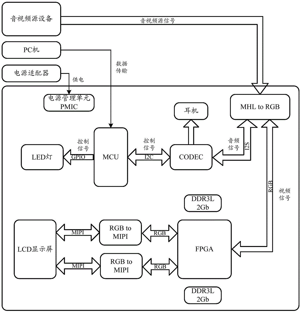

Image

  • Head-mounted display
  • Head-mounted display

Examples


Embodiment Construction

[0031] In order to make the object, technical solution and advantages of the present invention clearer, the implementation manner of the present invention will be further described in detail below in conjunction with the accompanying drawings.

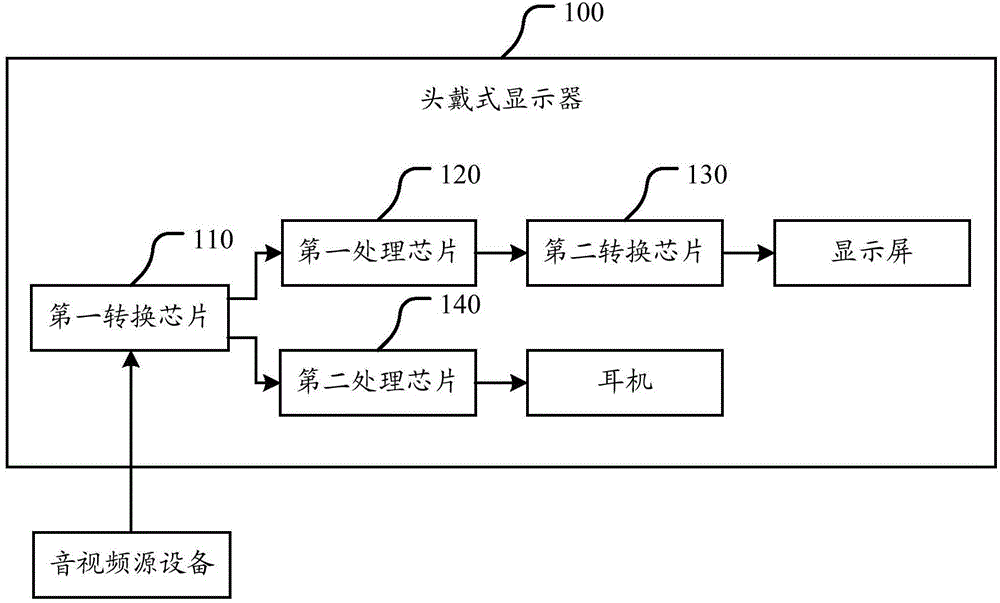
[0032] figure 1 A schematic diagram of a head-mounted display according to an embodiment of the present invention is shown. Such as figure 1 As shown, the head-mounted display 100 includes:

[0033] The first conversion chip 110 is used to convert the video signal in the audio and video source signal input by the external audio and video source equipment into an RGB (RGB color difference interface) signal, and output the RGB signal to the first processing chip 120; and for The audio signal in the input audio and video source signal is converted into an I2S (Inter-IC Sound, bus) signal, and the I2S signal is output to the second processing chip 140 .

[0034] The first processing chip 120 is configured to optimize the input RGB signa...


PUM


Abstract

The invention discloses a head-mounted display. The head-mounted display comprises a first conversion chip, a first processing chip, a second conversion chip and a second processing chip; the first conversion chip is used to convert a video signal in input audio and video source signals into an RGB signal and output the RGB signal to the first processing chip, and is used to convert an audio signal in the input audio and video source signals into an I2S signal and output the I2S signal to the second processing chip; the first processing chip is used to perform optical processing on the input RGB signal and output the processed RGB signal to the second conversion chip; the second conversion chip is used to convert the input RGB signal after the optical processing into a preset interface signal and output the preset interface signal to a display screen interface of the head-mounted display; and the second processing chip is used to perform decoding processing on the input I2S signal and output the processed I2S signal to an earphone interface of the head-mounted display According to the scheme, the audio and video signals can respectively be adapted to the display screen interface and the earphone interface of the head-mounted display and then be output, and perfect visual experience and perfect auditory experience are provided for a user.

Description

technical field [0001] The present invention relates to the technical field of visual equipment, in particular to a head-mounted display. Background technique [0002] With the development of science and technology, head-mounted displays have gradually become civilians, providing more and more people with high-quality visual and auditory effects. In the prior art, audio and video processing solutions for head-mounted displays mainly include two types: the first solution is to put mobile phones or other audio and video playback terminals directly on the front bracket of the head-mounted display, and other audio and video playback terminals output The audio and video of the audio and video are directly provided to the user, and the typical ones are Samsung Gear VR, Baofeng Mojing, etc.; The playback effect is limited by the processing effects of other audio and video playback terminals, which has great limitations in implementation and development. The second solution is tha...

Claims


Application Information

Patent Timeline
IPC IPC(8): G02B27/01H04N7/01
CPCG02B27/017G02B2027/014H04N7/01
Inventor 邓雪冰朱明代崇光
Owner BEIJING PICO TECH
Learn More