High-speed led optical communication resonant quasi-switching modulator

A technology of switch modulation and optical communication, applied in electromagnetic wave transmission systems, electrical components, transmission systems, etc., can solve the problems of low carrier recombination rate, long carrier annihilation time, poor optical communication effect, etc., and achieve optical communication Good communication effect, increase recombination rate, and reduce the effect of energy band bending

Active Publication Date: 2017-06-09
NJU OPTOELECTRONICS ENG RES INST CO LTD
View PDF6 Cites 0 Cited by
  • Summary
  • Abstract
  • Description
  • Claims
  • Application Information

AI Technical Summary

Problems solved by technology

LED is connected in series with a switch for simple modulation. The disadvantage is that the switching speed is severely limited, the carrier recombination rate is not high, and the remaining carrier annihilation time is too long, which makes the optical communication effect very poor.

Method used


Image

  • High-speed led optical communication resonant quasi-switching modulator
  • High-speed led optical communication resonant quasi-switching modulator
  • High-speed led optical communication resonant quasi-switching modulator

Examples


Embodiment 1

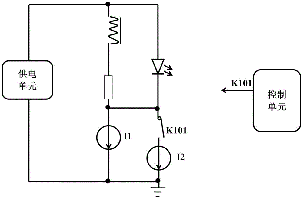
[0017] see figure 1 , this high-speed LED optical communication resonant quasi-switching modulator includes a power supply unit, an inductor, a resistance switch K101, LED, a current source I1, and a current source I2; the power supply unit is a voltage-limiting constant-current control unit, and the control unit is used to generate and output Control signal to realize timing control; the power supply unit, inductor, resistor and current source I1 are connected in series to form a loop; the anode of the LED is connected to the positive pole of the power supply unit, and the cathode is connected to the positive pole of the current source I2 through the switch K101; the negative pole of the current source I1 and the current source I2 The negative pole and the negative pole of the power supply unit are common ground; the cathode of the LED is connected to the positive pole of the current source I1;

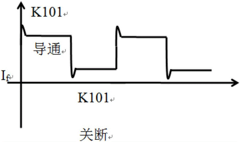
[0018] When the control unit sends a control signal to turn on the switch K101,...

Embodiment 2

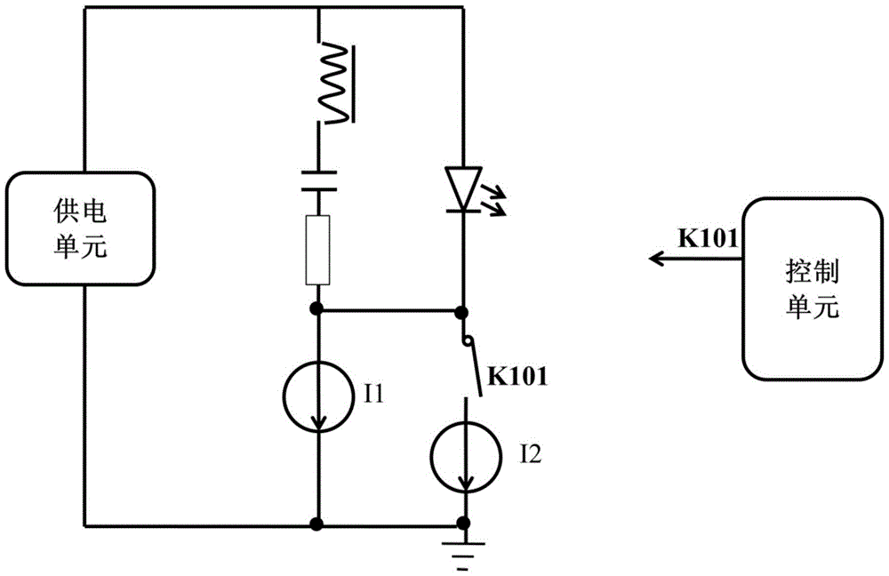
[0021] see figure 2 , the high-speed LED optical communication resonant quasi-switching modulator includes a power supply unit, an inductor, a capacitor, a resistance switch K101, an LED, a current source I1, and a current source I2; The unit is used to generate and output control signals to achieve timing control; the power supply unit, inductor, capacitor, resistor and current source I1 are sequentially connected in series to form a loop; the anode of the LED is connected to the positive pole of the power supply unit, and the cathode is connected to the positive pole of the current source I2 through the switch K101; The negative pole of the current source I1, the negative pole of the current source I2 and the negative pole of the power supply unit are common ground; the cathode of the LED is connected to the positive pole of the current source I1;

[0022] When the control unit sends out a control signal to turn on the switch K101, the voltage limiting constant current cont...


PUM


Abstract

The invention discloses a high-speed LED optical communication resonant quasi-switching modulator. The power supply unit is a voltage-limiting constant-current control unit, and the control unit is used to generate and output control signals to realize timing control; the power supply unit, inductance, resistance and current The source I1 is connected in series in sequence to form a loop; the anode of the LED is connected to the positive pole of the power supply unit, and the cathode is connected to the positive pole of the current source I2 through the switch K101; the cathode of the LED is connected to the positive pole of the current source I1; when the control unit sends a control signal to make the switch K101 turn on, the limit The voltage and constant current control unit supplies positive power to the LED to turn on the LED quickly; at the same time, the inductor stores energy; when the control unit sends a control signal and the switch K101 is turned off, the constant current drops, and the inductor generates a negative voltage. Reverse power supply to the LED during the falling time, so that the LED light intensity drops rapidly. The invention has fast switch and good optical communication effect.

Description

technical field [0001] The invention relates to an LED modulator, in particular to a high-speed LED optical communication resonant quasi-switching modulator. Background technique [0002] Optical communication is to achieve ultra-high-speed optical switching rate, rather than high-speed switching in common circuits. The emphasis here is on the switching rate of light, not the switching rate of electrons or holes; optical communication is used to supplement wireless communication applications such as WIFI Insufficient, in some areas to replace WIFI has become a new way of communication. LEDs are connected in series with a switch for simple modulation. The disadvantages are that the switching speed is severely limited, the carrier recombination rate is not high, and the remaining carrier annihilation time is too long, which makes the optical communication effect very poor. Contents of the invention [0003] The technical problem to be solved by the present invention is to p...

Claims


Application Information

Patent Timeline
Patent Type & Authority Patents(China)
IPC IPC(8): H04B10/516
Inventor 陈敦军雷建明谢自力
Owner NJU OPTOELECTRONICS ENG RES INST CO LTD
Why Eureka
Try Eureka