High-speed LED optical communication bridge-type modulator

A technology of optical communication bridges and modulators, applied in electromagnetic wave transmission systems, electrical components, transmission systems, etc., can solve the problems of low carrier recombination rate, long carrier annihilation time, poor optical communication effect, etc., and achieve Simple structure, good effect, reduce the effect of band bending

Active Publication Date: 2015-08-19
NJU OPTOELECTRONICS ENG RES INST CO LTD
View PDF5 Cites 0 Cited by
  • Summary
  • Abstract
  • Description
  • Claims
  • Application Information

AI Technical Summary

Problems solved by technology

The existing LEDs are connected in series with a switch for simple modulation. The disadvantages are that the switching speed is severely limited, the carrier recombination rate is not high, and the remaining carrier annihilation time is too long, which makes the optical communication effect very poor.

Method used


Image

  • High-speed LED optical communication bridge-type modulator
  • High-speed LED optical communication bridge-type modulator
  • High-speed LED optical communication bridge-type modulator

Examples


Embodiment 1

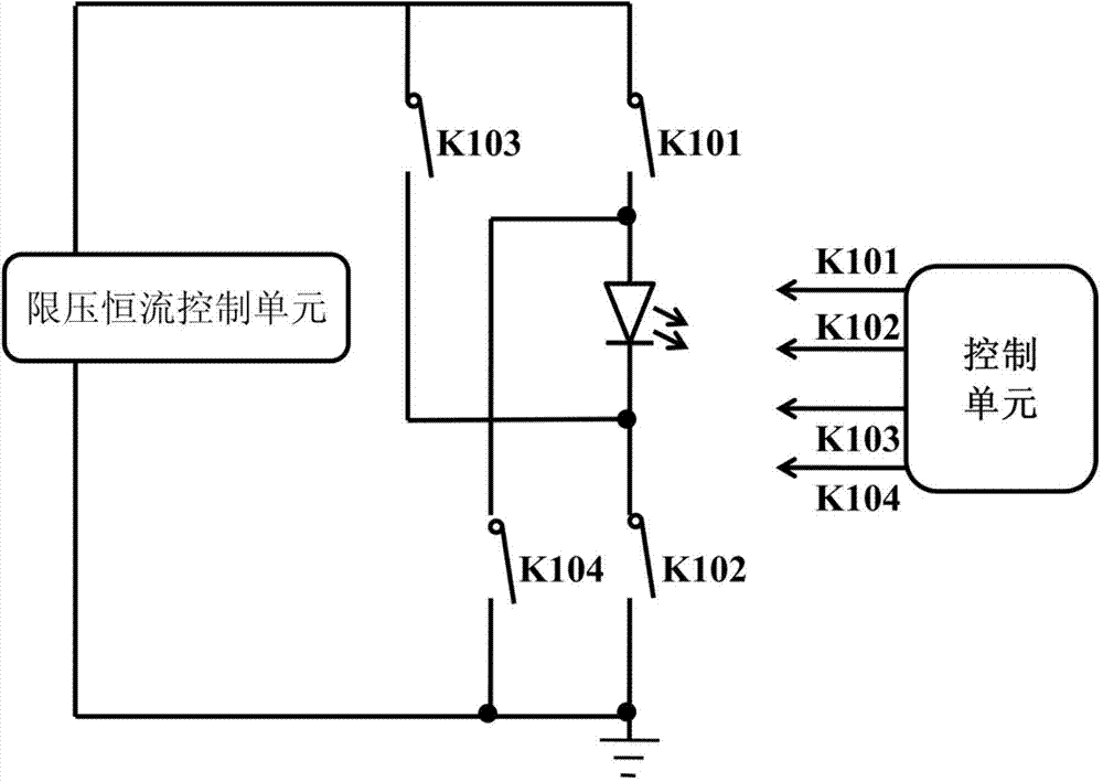
[0034] see figure 1 , the high-speed LED optical communication bridge modulator includes a power supply unit, LED, switch K101, switch K102, switch K103, switch K104 and a control unit; the power supply unit includes a voltage limiting constant current control unit; the control unit is used for Generate and output the control signal of the switch and realize the timing control; the timing control controls the reverse power supply time by monitoring the reverse current of the LED; the voltage limiting constant current control unit, the switch K101, the LED and the switch K102 are sequentially connected in series to form a loop The end of the switch K102 away from the cathode of the LED is grounded; one end of the switch K104 is connected to the anode of the LED, and the other end is grounded; one end of the switch K103 is connected to the cathode of the LED, and the other end is connected to the positive pole of the voltage limiting constant current control unit;

[0035] When...

Embodiment 2

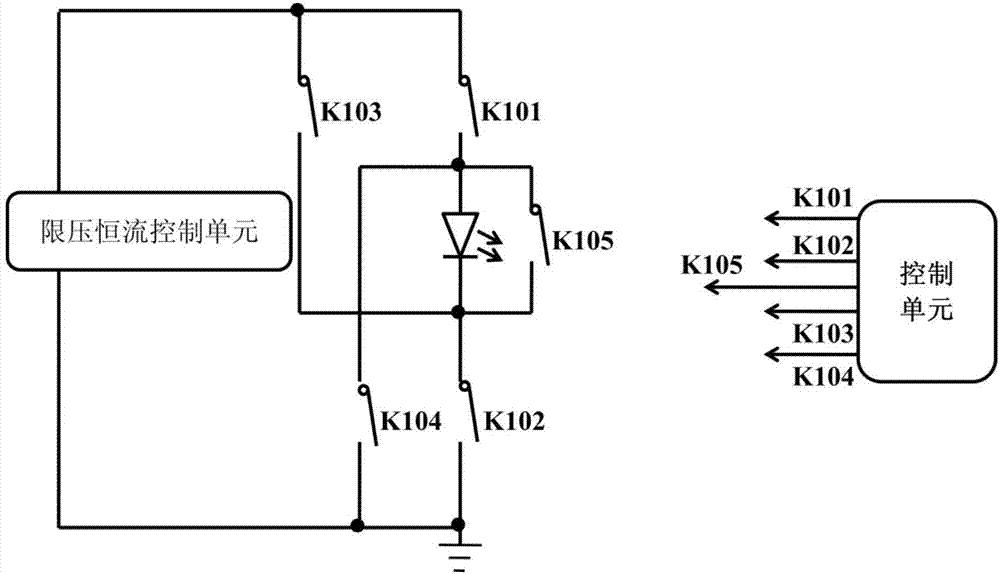
[0038] see figure 2 , the high-speed LED optical communication bridge modulator of the present invention includes a power supply unit, LED, switch K101, switch K102, switch K103, switch K104, switch K105 and a control unit; the power supply unit includes a voltage limiting and constant current control unit; The control unit is used to generate and output the control signal of the switch and realize the timing control; the timing control controls the reverse power supply time by monitoring the reverse current of the LED; the voltage limiting constant current control unit, the switch K101, the LED and the switch K102 A loop is formed in series in sequence; the end of the switch K102 away from the LED cathode is grounded; one end of the switch K104 is connected to the LED anode, and the other end is grounded; one end of the switch K103 is connected to the LED cathode, and the other end is connected to the positive pole of the voltage limiting constant current control unit; the sw...

Embodiment 3

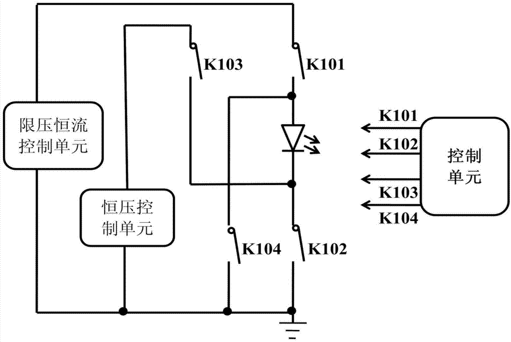
[0042] see image 3 , the high-speed LED optical communication bridge modulator includes a power supply unit, LED, switch K101, switch K102, switch K103, switch K104 and a control unit; the power supply unit includes a voltage limiting constant current control unit and a constant voltage control unit; The control unit is used to generate and output the control signal of the switch and realize the sequence control; the control of the sequence controls the reverse power supply time by monitoring the reverse current of the LED; the voltage limiting constant current control unit, the switch K101, the LED and the switch K102 is connected in series in turn to form a loop; the end of the switch K102 away from the LED cathode is grounded; one end of the switch K104 is connected to the LED anode, and the other end is grounded; one end of the switch K103 is connected to the LED cathode, and the other end is connected to the positive pole of the constant voltage control unit. The negativ...


PUM


Abstract

The invention discloses a high-speed LED optical communication bridge-type modulator, and the modulator comprises a power supply unit, an LED, a switch K101, a switch K102, a switch K103, a switch K104, a switch K105, a control unit, a voltage-limiting constant current control unit, and a constant voltage control unit. The switches K101 and K102 are connected, and the switches K103, K104 and K105 are disconnected. The forwarding power supply of the LED is carried out, thereby enabling the LED to be quickly overshot and connected. The switches K103 and K104 are connected, and the switches K101, K102 and K105 are disconnected. The reverse power supply of the LED is carried out, thereby enabling the LED to be quickly turned off. The control of time sequence controls the time of reverse power supply through the monitoring of a reverse current of the LED, and the reverse power supply is not carried out in the whole disconnection process but in a small time period, so as to prevent band bending from causing the great decrease of radiative recombination rate, and improving the disconnection speed of light. The switch K105 is connected, and the switches K101, K102, K103 and K104 are disconnected. The switch K105 is a discharge circuit which aims at speeding up the recombination of residual carriers of the LED, and controls the forwarding unidirectional discharge of the LED. The modulator improves the recombination speed of carriers, and is high in switching speed.

Description

technical field [0001] The invention relates to an LED modulator, in particular to a high-speed LED optical communication bridge modulator. Background technique [0002] Optical communication is to achieve ultra-high-speed optical switching rate, not the electrical high-speed switching in common circuits. The emphasis here is on the switching rate of light, not simply the switching rate of electrons or holes. Optical communication is used to supplement the shortcomings of wireless communication applications such as WIFI, and replace WIFI in some fields to become a new communication method. LED optical communication technology is a brand-new communication technology that has gradually developed in recent years. Many related technical researches are still in their infancy, especially in the technology of high-speed LED devices and high-speed switching circuits. The existing LEDs are connected in series with a switch for simple modulation. The disadvantages are that the switch...

Claims


Application Information

Patent Timeline
Patent Type & Authority Applications(China)
IPC IPC(8): H04B10/516
Inventor 陈敦军雷建明谢自力
Owner NJU OPTOELECTRONICS ENG RES INST CO LTD
Why Eureka
Try Eureka