A distributed feedback laser chip and its preparation method

A distributed feedback and laser technology, applied in lasers, laser components, semiconductor lasers, etc., can solve the problems of severe thermal effects, large laser material stress, large device series resistance, etc., to enhance internal quantum efficiency and suppress non-radiative recombination , the effect of increasing the modulation rate

Active Publication Date: 2021-09-28
因林光电科技(苏州)有限公司
View PDF3 Cites 0 Cited by
  • Summary
  • Abstract
  • Description
  • Claims
  • Application Information

AI Technical Summary

Problems solved by technology

Conventional DFB lasers all use masked gratings, which require multiple epitaxial growths. The preparation process is complicated, and the interface of the secondary epitaxial growth is prone to contamination, which seriously affects the performance and reliability of the laser, and the preparation cost is high, which is not conducive to mass production. Production
Some existing DFB lasers use one-time epitaxial growth, and prepare gratings on the surface of the laser through micro-nano processing technology. Since the grating reduces the current injection area, the series resistance of the device is large, and the thermal effect is serious, which seriously affects the performance and reliability of the device.
[0004] Conventional DFB lasers use AlGaAsP or InP optical field confinement layer with high Al composition, and the optical field confinement layer is thicker (about 3 μm), resulting in greater stress in the laser material
The laser chip usually adopts a double-groove structure in order to suppress the lateral multi-mode. Because the channel of the double-groove is very narrow, the optical field confinement layer of high Al composition AlGaAsP or InP in the laser chip is still relatively thick, and the stress in the laser material is still relatively large. , in the process of laser testing and chip preparation after epitaxial growth, it is easy to crack and fragment, which seriously affects the production yield and device reliability

Method used


Image

  • A distributed feedback laser chip and its preparation method
  • A distributed feedback laser chip and its preparation method
  • A distributed feedback laser chip and its preparation method

Examples


Embodiment Construction

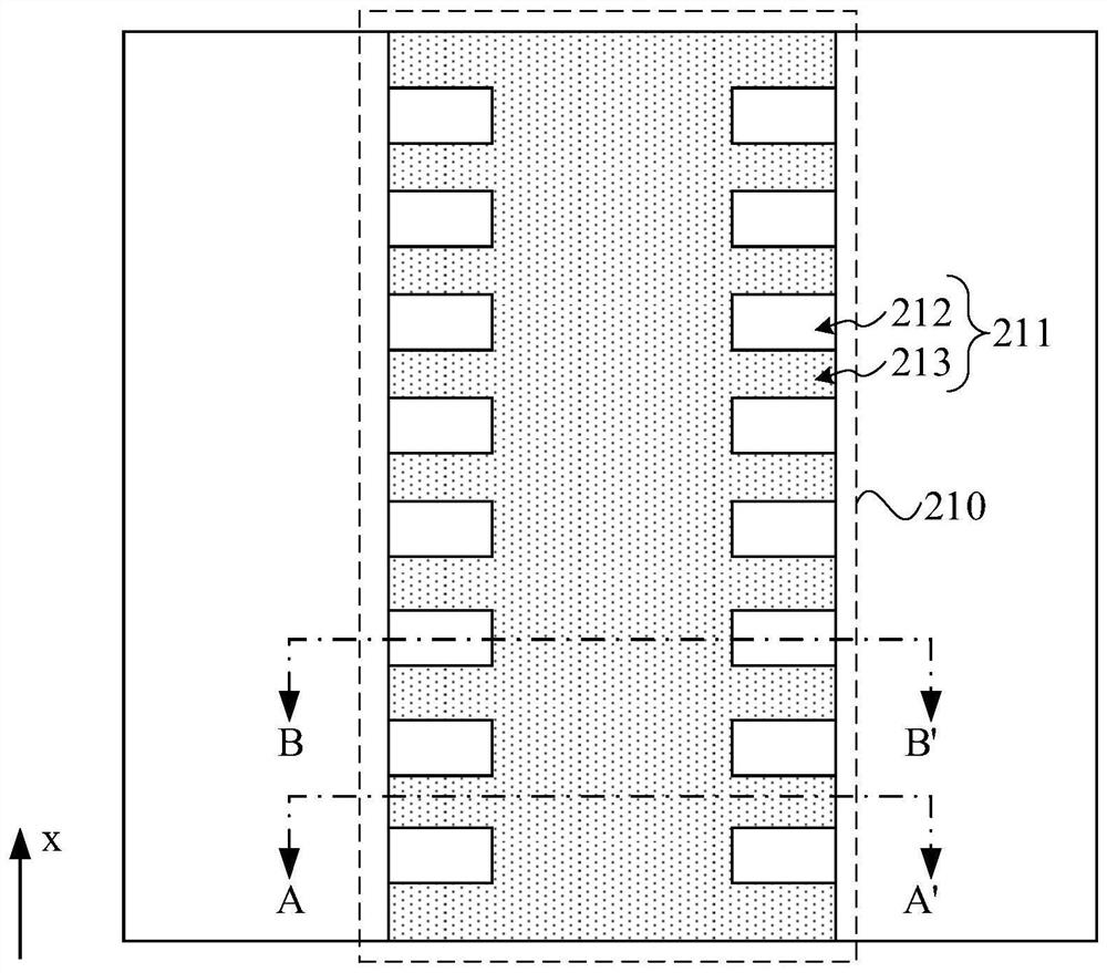
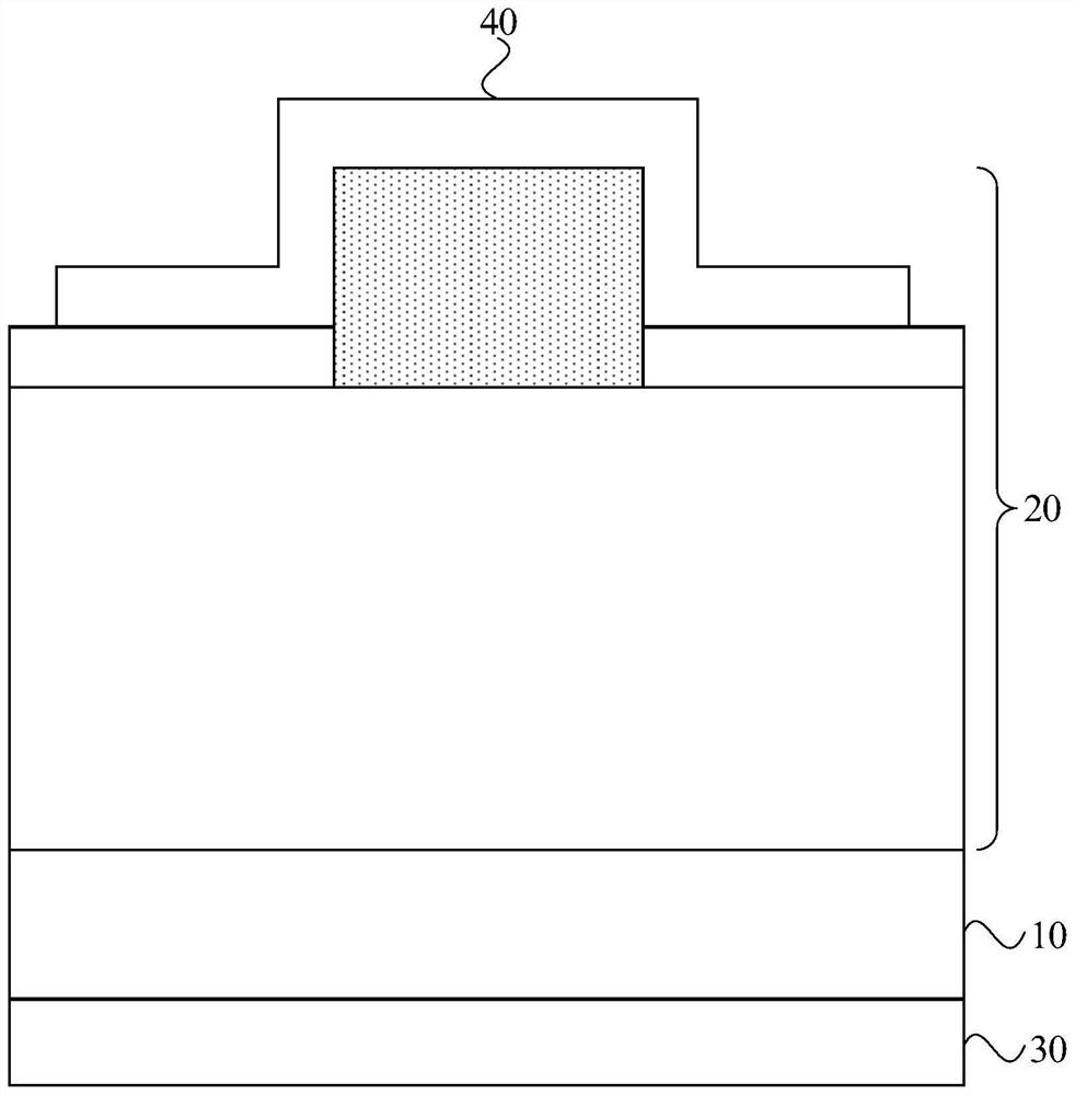
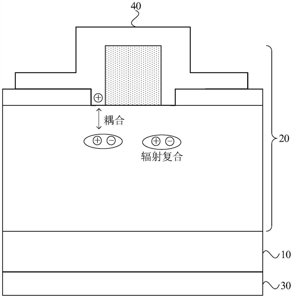
[0041] The present invention will be further described in detail below in conjunction with the accompanying drawings and embodiments. It should be understood that the specific embodiments described here are only used to explain the present invention, but not to limit the present invention. In addition, it should be noted that, for the convenience of description, only some structures related to the present invention are shown in the drawings but not all structures.

[0042] Terms used in the embodiments of the present invention are only for the purpose of describing specific embodiments, and are not intended to limit the present invention. It should be noted that the orientation words such as "up", "down", "left", and "right" described in the embodiments of the present invention are described from the angles shown in the drawings, and should not be interpreted as a reference to the implementation of the present invention. Example limitations. Also in this context, it also nee...


PUM

PropertyMeasurementUnit
sizeaaaaaaaaaa
sizeaaaaaaaaaa

Abstract

The embodiment of the invention discloses a distributed feedback laser chip and a preparation method thereof. Wherein the laser chip includes a substrate, a laser structure on one side of the substrate, a first electrode, and a second electrode; a grating pattern is arranged on the side adjacent to the second electrode of the laser structure, and the grating pattern includes a ridge structure, and the ridge structure It includes a first region and a second region arranged circularly along the first direction, the refractive index of the first region is greater than that of the second region; the second electrode covers the ridge structure and extends to a part of the second region, and The film layer where the grating pattern is located is in contact with the film layer on the side close to the substrate; wherein, the first direction is parallel to the plane where the substrate is located. The technical solution of the embodiment of the present invention has the advantages of high modulation rate, high internal quantum efficiency, low resistance, good single-mode characteristics, small stress, and low cost, and can greatly improve the modulation rate, electro-optical conversion efficiency, single-mode performance and Production yield, etc., are very conducive to mass production applications.

Description

technical field [0001] Embodiments of the present invention relate to semiconductor laser technology, and in particular to a distributed feedback laser chip and a manufacturing method thereof. Background technique [0002] With the development of high-speed optical communication systems, high transmission rates have become an urgent need for optical fiber transmission systems. Among them, high-speed semiconductor laser chips are the core. Improving the transmission rate of semiconductor laser chips can greatly increase the transmission rate of optical fibers. Distributed Feedback (DFB) laser has good single-mode characteristics and high modulation rate, so it has become a common semiconductor light source for optical fiber communication, and has attracted extensive attention from industry and academia. [0003] For DFB lasers, the recombination rate of the internal carriers determines the modulation rate of the laser to a large extent, and the carriers in the laser mainly un...

Claims


Application Information

Patent Timeline
Patent Type & Authority Patents(China)
IPC IPC(8): H01S5/12H01S5/22H01S5/042H01S5/343
CPCH01S5/12H01S5/22H01S5/343H01S5/04252
Inventor 刘朝明王涛高磊张峰
Owner 因林光电科技(苏州)有限公司
Why Eureka
Try Eureka