Adjustable fixture used for wet etching anisotropic velocity test of hemispheric test piece

A wet etching and anisotropic technology, applied in workpiece clamping devices, manufacturing tools, etc., can solve the problems of lack of efficient and practical special fixtures for spherical crystal materials, lack of positioning and protection of the bottom surface of the sphere, and poor versatility. , to avoid unreliable clamping, reduce experimental costs, and avoid falling off and displacement.

Active Publication Date: 2015-09-23
SOUTHEAST UNIV
View PDF6 Cites 1 Cited by
  • Summary
  • Abstract
  • Description
  • Claims
  • Application Information

AI Technical Summary

Problems solved by technology

At present, the wet etching of flake crystal materials at home and abroad has gradually formed unified and standardized special fixtures, such as electrostatic adsorption clamping fixtures and vacuum adsorption clamping fixtures, etc. However, wet etching for spherical crystal materials has still not appeared. Efficient and practical special fixtures. Most of the currently known spherical crystal material fixtures have complex structures, poor versatility, and do not have the functions of positioning and protecting the bottom surface of the sphere.

Method used


Image

  • Adjustable fixture used for wet etching anisotropic velocity test of hemispheric test piece
  • Adjustable fixture used for wet etching anisotropic velocity test of hemispheric test piece
  • Adjustable fixture used for wet etching anisotropic velocity test of hemispheric test piece

Examples


Embodiment Construction

[0023] The present invention will be further described below in conjunction with the embodiments and the accompanying drawings.

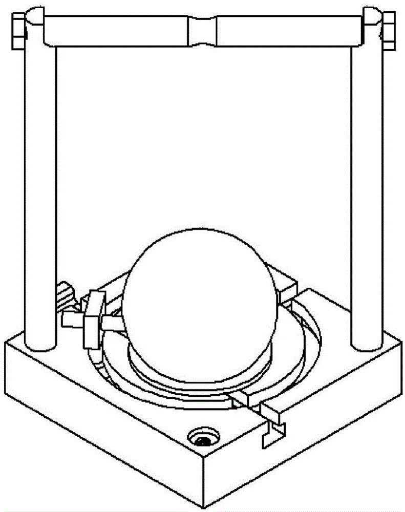
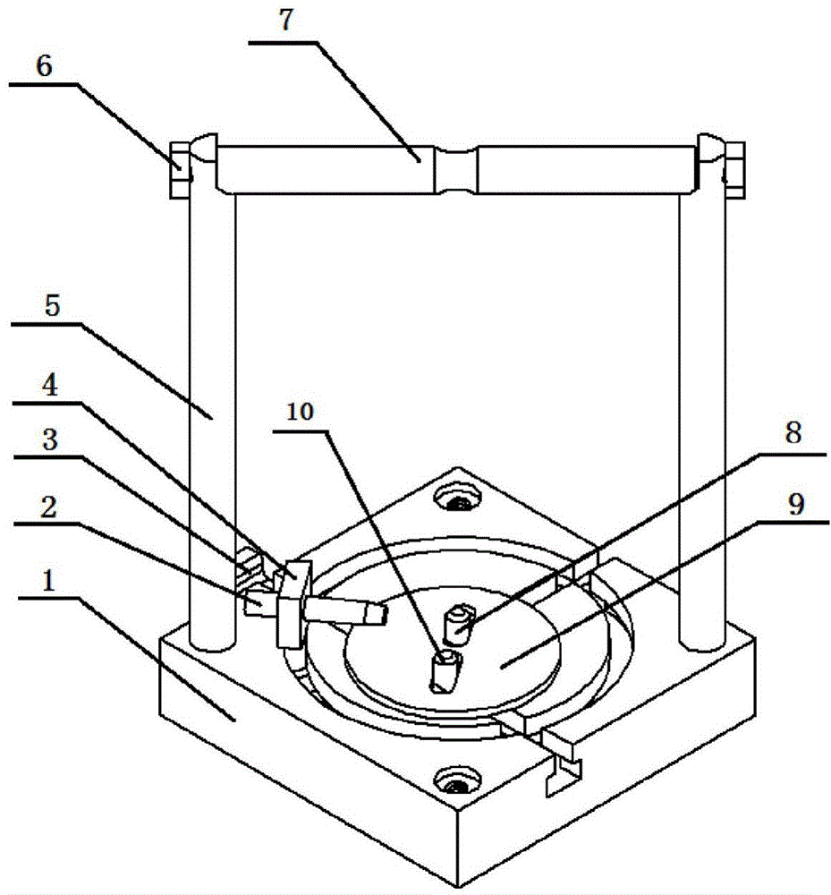
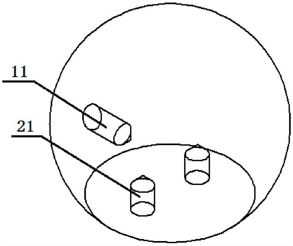
[0024] The adjustable fixture used for the wet etching anisotropy rate test of the hemispherical specimen of the present invention includes: a positioning and clamping module, a spherical bottom protection module and an extraction module, wherein all parts are made of corrosion-resistant and high-temperature-resistant , Made of Teflon plastic with certain elasticity. In the positioning and clamping module, the base 1 is provided with a full-through straight T-slot 13, a half-through straight T-slot 14 and a circular T-slot 15, and the circular T-slot 15 takes the centroid of the base surface as the center of the circle. , and make the sliding nail base 4 relatively slide inside it, the half-through linear T-slot 14 is located on the center line of the base and extends to the center of the base, the full-through straight T-slot 13 is perpendicular to...


PUM


Abstract

The invention discloses an adjustable fixture used for a wet etching anisotropic velocity test of a hemispheric test piece. The adjustable fixture comprises a base, sliding nails, a fastening stopper, a combined sliding nail and a sphere bottom supporting sheet, wherein a hand-basket handle adopts a structure with two vertical rods and a cross beam; an arc thin waist is arranged in the middle of the cross beam; two vertically distributed straight T-shaped grooves and a circle of circular T-shaped groove are formed in the base; during clamping, the sliding nail in the half-through straight T-shaped groove is pushed to the arc end face, then the sliding nail in the full-through straight T-shaped groove is slid to allow the distances between the two sliding nails and two bottom holes of an etching sphere to be consistent; then the two sliding nails are pressed into the bottom holes of the etching sphere; finally the fastening stopper is pushed into the full-through straight T-shaped groove to push against the sliding nails till no movement occurs, thereby realizing the locating and clamping in the horizontal direction; the combined sliding nail slides in the circular T-shaped groove, and after the position of the combined sliding nail and the position of a side hole of the etching sphere are consistent, a clamping pin is inserted into the side hole of the etching sphere, thereby clamping the sphere in the vertical direction; and the sphere bottom supporting sheet is used for protecting the bottom surface of the etching sphere, and uniformly adhered to the bottom surface of the sphere by W-type apiezon wax before clamping.

Description

technical field [0001] The invention belongs to the technical field of clamping and fixing processing materials in micro-electromechanical manufacturing systems, and relates to a positioning and clamping device for spherical crystal materials in anisotropic wet etching. Background technique [0002] In the wet etching system, the etching objects are often in harsh etching environments such as strong acid and alkali, high temperature, stirring, and ultrasonic waves. Therefore, the positioning and clamping of the etching objects directly affects the etching accuracy and the accuracy of data measurement. . Good clamping equipment can not only greatly improve the etching efficiency, precision and accuracy of results, but also greatly facilitate the measurement of data results after etching. Therefore, whether the clamping equipment is matched or not is directly related to wet etching. The pros and cons of eclipse results. At present, the wet etching of flake crystal materials ...

Claims


Application Information

Patent Timeline
Patent Type & Authority Applications(China)
IPC IPC(8): B25B11/00
CPCB25B11/00
Inventor 幸研张辉李源
Owner SOUTHEAST UNIV
Why Eureka
Try Eureka