Method for designing die molded surface for forming groove-shaped part

A technology of mold surface and design method, applied in the field of grooved parts forming, can solve the problems of high professional knowledge requirements, cumbersome modeling work, and many iterations.

Inactive Publication Date: 2015-09-23
NORTHWESTERN POLYTECHNICAL UNIV +1
View PDF5 Cites 8 Cited by
  • Summary
  • Abstract
  • Description
  • Claims
  • Application Information

AI Technical Summary

Problems solved by technology

[0006] In order to overcome the shortcomings of cumbersome modeling work, many iterations, large amount of calculation, and high professio

Method used


Image

  • Method for designing die molded surface for forming groove-shaped part
  • Method for designing die molded surface for forming groove-shaped part
  • Method for designing die molded surface for forming groove-shaped part

Examples


Embodiment Construction

[0041] An embodiment is a method of designing a mold surface for forming a channel.

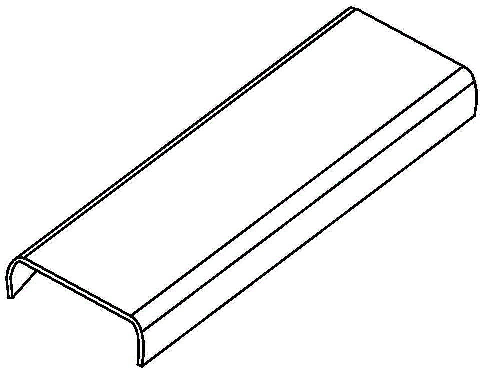
[0042] Such as figure 1 As shown, the cross-section of the composite channel member formed by the mold is concave, and the groove surface of the concave shape is the inner surface.

[0043] The material of the part to be formed is a composite material. The material of the composite groove part is selected as prepreg AS4 / 8552, and the thermal expansion coefficient of the composite fiber direction is a L is 0×10 -6 , the coefficient of thermal expansion in the thickness direction of the composite material a T 32.6×10 -6 , the fiber direction chemical shrinkage coefficient of the composite material is 0, the chemical shrinkage coefficient in the thickness direction of the composite material is 0.0048. The range of forming temperature ΔT is 160°C.

[0044] The length L of the part to be formed is 1000mm, the width of the groove is 300mm, and the height of the two side wall plates is 100...


PUM


Abstract

Disclosed is a method for designing a die molded surface for forming a groove-shaped part. An inner molded surface M of the part is extracted, and section lines Pj of the extracted inner molded surface of the part are manufactured; the various section lines Pj are corrected sequentially through correction basis points, and new section lines are obtained; and surface fitting is carried out on the obtained section lines, and a new mold outer molded surface is obtained. The maximum deformation of the groove-shaped part formed through the mold outer molded surface determined through the method is reduced to 0.2mm from 1.5mm, and the design requirements of the part are met. Compared with the traditional technology, when the mold molded surface is designed, rebound deformation obtained after part deformation is considered in the method, and the problem that according to a traditional method, an inner molded surface of a composite material groove-shaped part is directly extracted to serve as the mold molded surface for manufacturing the composite material part, the part size cannot meet the design requirement is solved; and the mold repairing frequency of a follow-up mold is reduced, and therefore the production manufacturing cost is reduced, and the production efficiency is improved.

Description

technical field [0001] The invention relates to the field of forming grooved parts, in particular to a method for designing mold profiles of composite material grooved parts. Background technique [0002] Advanced composite material is a high-performance material developed to meet the needs of high-tech fields such as aviation and aerospace. It has superior properties such as light weight, high strength and strong designability. In recent years, there has been an increasing demand for advanced composite materials in the aerospace and aviation fields. They are used as load-bearing structural parts to solve technical difficulties that cannot be solved by a single material, and are widely used in aircraft vertical stabilizers, fuselages, wings and other structures. . [0003] Autoclave forming technology is one of the widely used forming methods for advanced composite material structures used in aerospace. Its advantages are uniform pressure and temperature in the tank, low po...

Claims


Application Information

Patent Timeline
IPC IPC(8): B29C70/54B29C70/44B29C33/38
CPCB29C33/3835B29C70/44B29C70/54
Inventor 元振毅王永军魏生民杨绍昌苏霞王浩军雷杨魏俊鹏郭俊刚赵国强
Owner NORTHWESTERN POLYTECHNICAL UNIV
Why Eureka
Try Eureka