Sanding system of sanding machine

A sanding machine and sanding technology are applied in textiles and papermaking, roughening, fabric surface trimming, etc., which can solve problems such as lowering production quality, uneven tension, and increasing motor power, so as to solve uneven tension, assembly and Easy maintenance and improved work efficiency

Active Publication Date: 2015-09-23
GUANGDONG RUITUO ENVIRONMENTAL PROTECTION MACHINERY
View PDF8 Cites 6 Cited by
  • Summary
  • Abstract
  • Description
  • Claims
  • Application Information

AI Technical Summary

Problems solved by technology

[0002] The brush drum of the sanding machine is the core component of the whole sanding machine. The structure of the brush drum, especially the number of brush rollers, directly determines the sanding effect; the more the number of brush rollers, the larger the path angle of the cloth. The closer the path on the brush drum is to a circle, if the pressure of the cloth and the brush roller wants to achieve the same effect, the tension of the whole cloth must be increased, which will not only increase the power of the motor, but also make the cloth Excessive deformation will affect the sanding effect
In addition, before the cloth enters the brush roller, it passes through the adjustment plate, and the cloth will be further opened after passing through the adjustment plate. If the angle between the path of the cloth is too large, the impact on the cloth will be small when the brush drum rotates, which is not conducive to the unfolding of the cloth.
[0003] The traditional sanding machine is not equipped with a tension sensor and a driving roller on the brush drum, which will lead to uneven tension of the cloth on the brush drum. To obtain the same sanding effect, the tension of the cloth must be increased. It will increase the power of the motor, resulting in excessive stretching of the cloth, which often brings various creases and reduces the production quality when knitting fabrics and other sensitive fabrics with elasticity

Method used


Image

  • Sanding system of sanding machine
  • Sanding system of sanding machine
  • Sanding system of sanding machine

Examples


Embodiment Construction

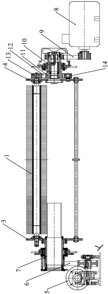
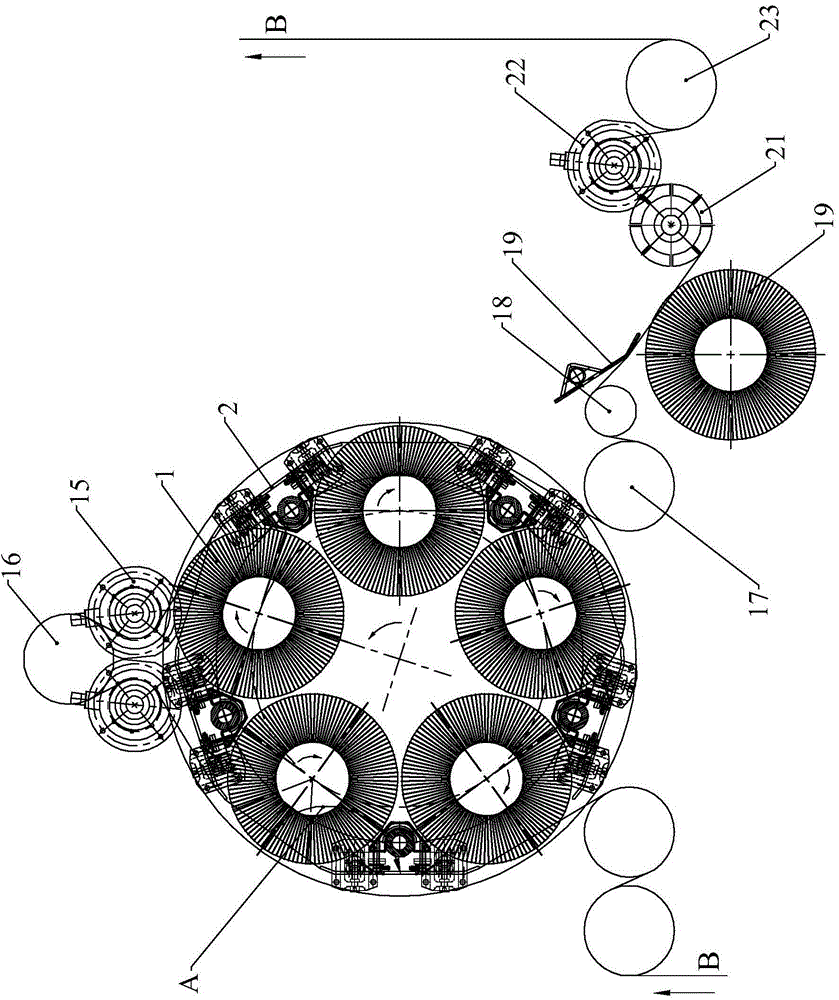
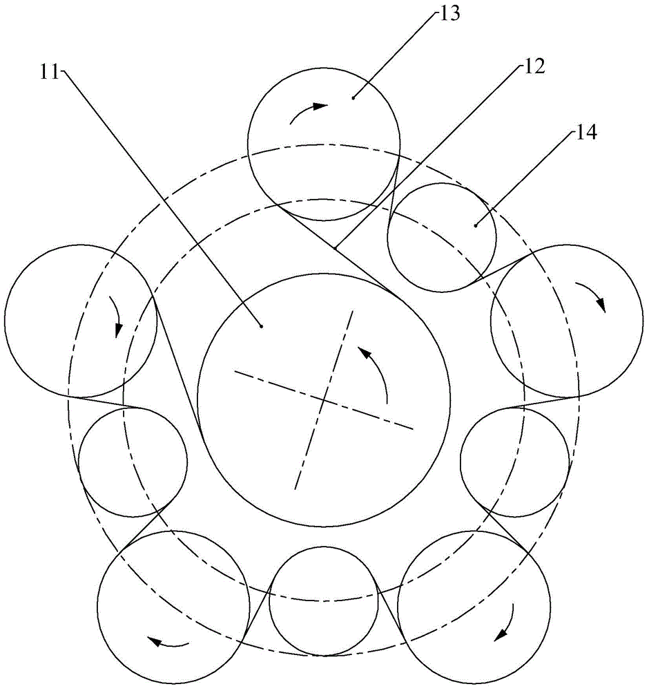
[0022] refer to Figure 1 to Figure 3 , the present embodiment includes a brush drum, a brush drum driving device, a brush roller driving device, a brush roller synchronous rotation device and a brushing finishing device; the brush drum includes five brush rollers 1 and five sets of adjustment plate devices 2 , the five brush rollers are uniformly arranged in a planetary structure and erected horizontally on the left support plate 3 and right support plate 4 of the brush drum, and the adjustment plate device is installed between two adjacent brush rollers; the brush drum driving device Arranged on the left side of the brush drum, the brush drum motor 5 drives the brush drum transmission device 7 through the brush drum synchronous belt 6 to form a brush drum driving device; the brush roller driving device is arranged on the right side of the brush drum, The brush roller driving device includes a brush roller motor 8, a transmission belt 9 and a brush roller transmission device ...


PUM


Abstract

The invention relates to a sanding system of a sanding machine. The sanding system comprises a brush drum, a brush drum drive device, a brush roller drive device, a brush roller synchronous rotation device and a sanding arrangement device. The brush drum comprises five brush rollers and five adjustment plate devices. The five brush rollers are arranged on a left supporting plate and a right supporting plate through even distribution and arrangement frames of planet structures. The adjustment plate devices are arranged between the adjacent brush rollers. A brush drum motor drives a brush drum transmission device to form the brush drum drive device through a brush drum synchronous belt. The brush roller motor drives a brush roller transmission device through a synchronous belt. A main transmission belt wheel of the brush roller synchronous rotation device is driven by the brush roller transmission device. A brush roller double-sided synchronous belt changes the direction through tensioning belt wheels and drives five brush roller transmission belt wheels to synchronously rotate. An outlet drive roller of the sanding arrangement device drives sanding cloth to be subjected to sanding arrangement through the outlet brush roller by means of a cloth guide roller and an adjustment pressing plate. The sanding system has the advantages of being capable of saving energy, convenient to install and detach and good in sanding effect.

Description

technical field [0001] The invention relates to a sanding system of a sanding machine. Background technique [0002] The brush drum of the sanding machine is the core component of the whole sanding machine. The structure of the brush drum, especially the number of brush rollers, directly determines the sanding effect; the more the number of brush rollers, the larger the path angle of the cloth. The closer the path on the brush drum is to a circle, if the pressure of the cloth and the brush roller wants to achieve the same effect, the tension of the whole cloth must be increased, which will not only increase the power of the motor, but also make the cloth If the deformation is too large, it will affect the sanding effect. In addition, the cloth passes through the adjustment plate before entering the brush roller, and the cloth will be further opened after passing through the adjustment plate. If the included angle of the path of the cloth is too large, the impact on the clot...

Claims


Application Information

Patent Timeline
Patent Type & Authority Applications(China)
IPC IPC(8): D06C11/00
CPCD06C11/00
Inventor 许艳萍戴立国林卓峰王刚容文劲
Owner GUANGDONG RUITUO ENVIRONMENTAL PROTECTION MACHINERY
Why Eureka
Try Eureka