Formwork system and cast-in-place concrete floor

A technology of cast-in-place concrete floor slabs and reinforced concrete floor slabs, which is applied in the field of cast-in-place concrete floor slabs, can solve problems such as many disadvantages, and achieve the effects of low cost, light weight, and convenient assembly and disassembly

Active Publication Date: 2017-03-01
张玉华
View PDF7 Cites 0 Cited by
  • Summary
  • Abstract
  • Description
  • Claims
  • Application Information

AI Technical Summary

Problems solved by technology

Technical schemes such as non-demolition formwork or filling blocks can be used in densely ribbed slabs. The usual construction methods require on-site aerial installation and other operations, which have many disadvantages

Method used


Image

  • Formwork system and cast-in-place concrete floor
  • Formwork system and cast-in-place concrete floor
  • Formwork system and cast-in-place concrete floor

Examples


Embodiment Construction

[0054] The present invention will be described in detail below in conjunction with the accompanying drawings and specific embodiments.

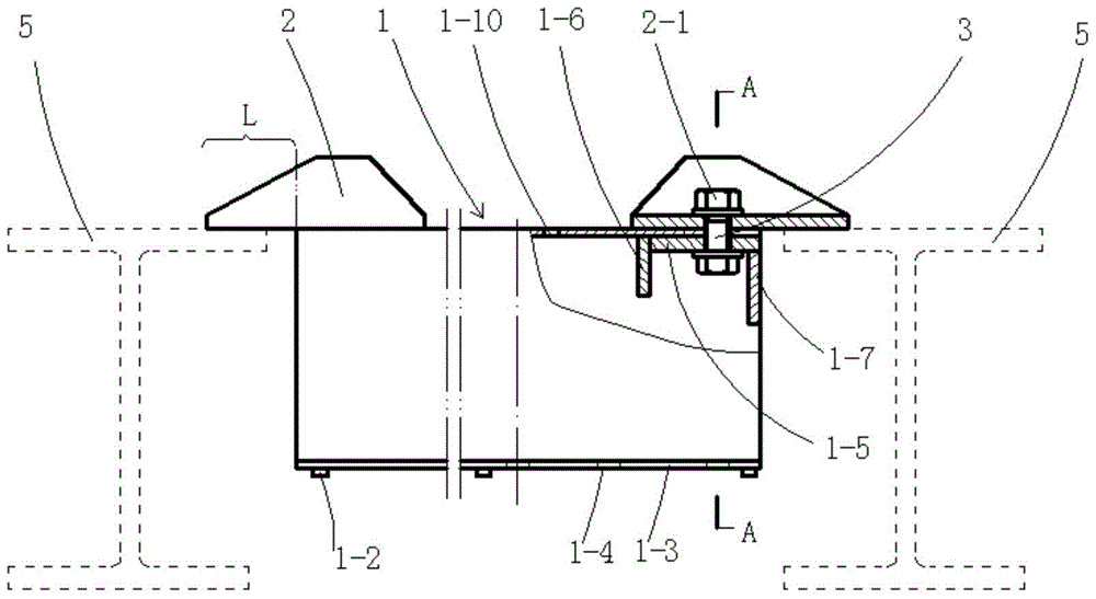
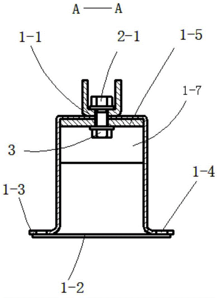
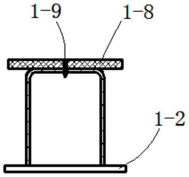
[0055] Template system embodiment 1, such as Figure 1-7 , including joist 1, template 6, figure 1 and figure 2 The joist 1 shown is a hat-shaped steel beam with a through hole 1-1 at the top, and the reinforcement structure at the end includes a reinforcement plate 1-5, a first reinforcement rib 1-6, and a second reinforcement rib 1-7 , horizontal bars 1-2 are arranged at intervals at the bottom; there are folded edges 1-3 at the lower part of the hat-shaped steel beam, and small holes a1-4 are arranged on the folded edges 1-3. The cantilever 2 is a U-shaped steel part, the two ends of the vertical bar are chamfered or chamfered, and there is an opening in the middle. The nut 2-1 is arranged on the opening, and the bolt 3 passes through the through hole 1-1, and the nut 2-1 1 Tighten the joist 1 and the cantilever 2, the bolt 3 can be di...


PUM


Abstract

The invention discloses a template system used for a cast-in-situ concrete floor. The template system comprises a template and multiple parallel joists. The end head of at least one joist is provided with a cantilever beam remained in the floor. The cantilever beams are steel components and protrude from the end heads of the joists, the protruded parts of the cantilever beams serve as lapping portions, and the other parts of the cantilever beams are laminated on the top surfaces of the joists and are in detachable connection with the joists through fasteners. The template system can be rapidly installed, has no vertical support, or only has a few of supports. The invention also discloses the cast-in-situ concrete floor, the multiple cantilever beams are arranged at intervals at floor supporting portions, the cantilever beams are the steel components, parts of the cantilever beams are arranged on steel beams or precast concrete beams or precast reinforced concrete shear walls which supporting the floor, and downwardly-through screw holes d and nuts are arranged near the external of a supporting seat. The cast-in-situ concrete floor is convenient to construct and is low in comprehensive cost.

Description

technical field [0001] The invention belongs to the technical field of construction, and relates to a formwork system, and also relates to a cast-in-place concrete floor slab. Background technique [0002] The formwork of the cast-in-place concrete floor slab is generally supported by full-scale scaffolding, which has mature technology and high reliability, but the process is complicated, the materials used are large, and the cost is high. [0003] One of the ways to improve is to use prefabricated laminated slabs instead of templates. However, prefabricated laminated floor slabs are heavy in weight, high in cost, and slightly poor in integrity. At the same time, when it is supported on the prefabricated reinforced concrete shear wall, the shelving length is limited by its exposed steel bars, which interacts with the prefabricated reinforced concrete shear wall. [0004] The second improvement method is to use a horizontal support formwork system, that is, the formwork is ...

Claims


Application Information

Patent Timeline
Patent Type & Authority Patents(China)
IPC IPC(8): E04G11/36E04G11/48E04G11/50E04G11/56E04G17/18E04B5/18E04G11/40
Inventor 张玉华
Owner 张玉华
Why Eureka
Try Eureka