Actuator motion control

A technology of actuators and electromagnetic actuators, applied in engine control, electrical control, fuel injection control, etc., can solve problems such as armature movement and inaccurate position estimation

Active Publication Date: 2015-09-23
GM GLOBAL TECH OPERATIONS LLC
View PDF6 Cites 5 Cited by
  • Summary
  • Abstract
  • Description
  • Claims
  • Application Information

AI Technical Summary

Problems solved by technology

As a result, relying solely on the current applied to the solenoid device can lea...

Method used


Image

  • Actuator motion control
  • Actuator motion control
  • Actuator motion control

Examples


Embodiment Construction

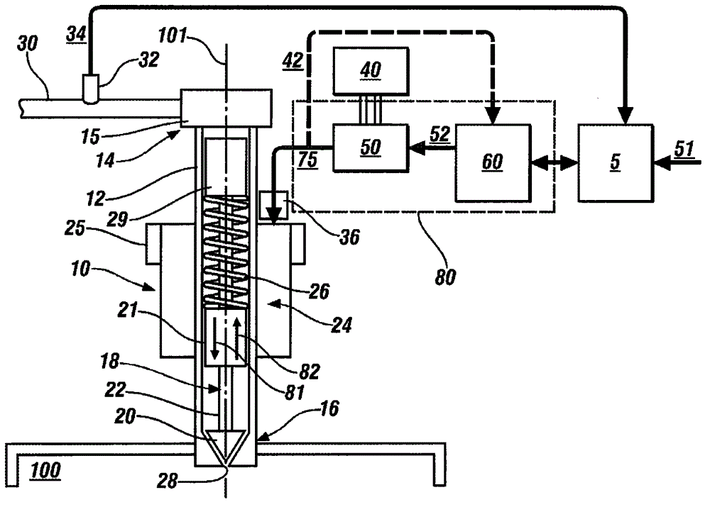
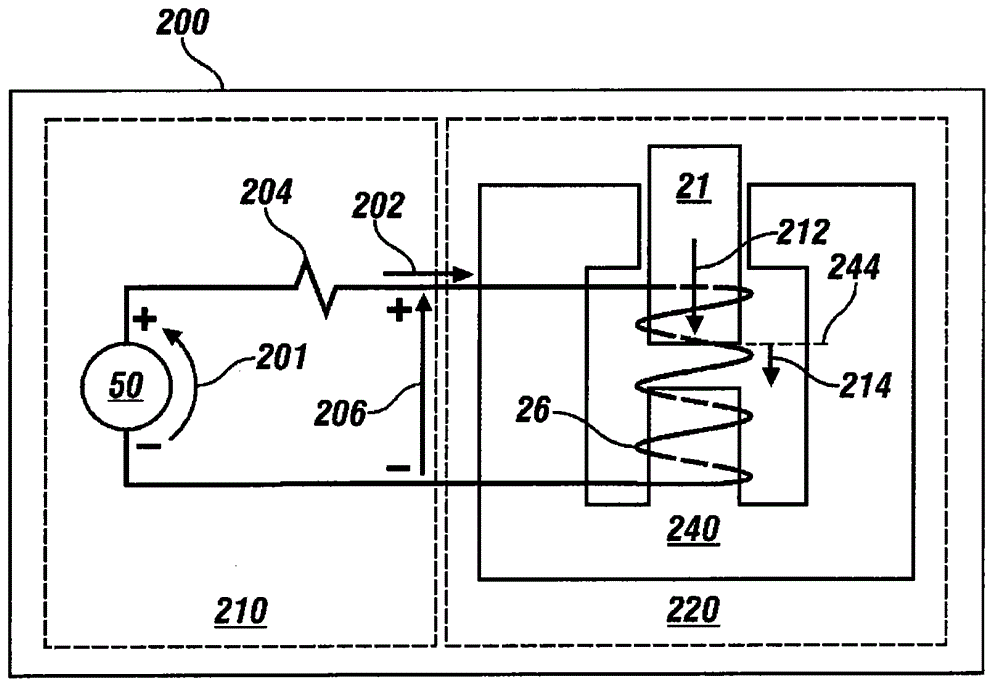
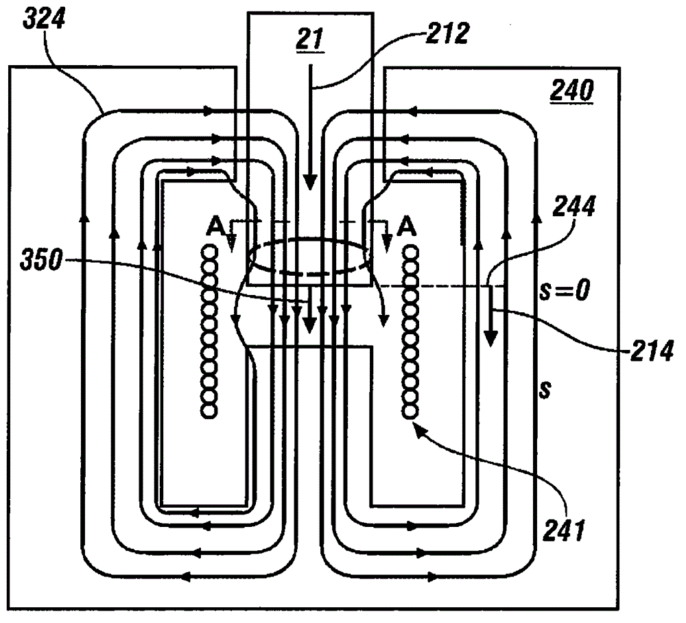
[0076] This disclosure describes the concepts of the presently claimed subject matter in connection with an exemplary application to a linear motion fuel injector. However, the claimed subject matter applies more broadly to any linear or nonlinear electromagnetic actuator employing an electrical coil that induces a magnetic field within a magnetic core to generate an attractive force on a movable armature. Typical examples include fluid control solenoids, gasoline or diesel or CNG fuel injectors employed on internal combustion engines, and non-fluid solenoid actuators for positioning and control.

[0077] Referring now to the drawings, in which the illustrations are for the purpose of illustrating certain exemplary embodiments only and not for the purpose of limiting these embodiments, figure 1 A non-limiting exemplary embodiment of an electromagnetically activated direct injection fuel injector 10 is schematically shown. While solenoid activated direct injection fuel injecto...


PUM


Abstract

A system for controlling actuation of an electromagnetic actuator includes an actuator having an electrical coil, a magnetic core, and an armature. A controllable drive circuit is responsive to an electric power flow signal for driving current through the electrical coil to actuate the armature. A control module includes an armature motion observer configured to determine an armature motion parameter in the actuator based upon a magnetic flux within the actuator and a predetermined mechanical equation of motion corresponding to the actuator and adapt the electric power flow signal based on the armature motion parameter.

Description

[0001] Cross References to Related Applications [0002] This application claims the benefit of US Provisional Application No. 61 / 955963, filed March 20, 2014, and US Provisional Application No. 61 / 955942, filed March 20, 2014, both of which are incorporated herein by reference. technical field [0003] The present disclosure relates to solenoid activated actuators. Background technique [0004] The statements in this section merely provide background information related to the present disclosure. Accordingly, such statements are not intended to constitute admissions of prior art. [0005] Solenoid actuators can be used to control fluids (liquids and gases), either for positioning or for control functions. A typical example of a solenoid actuator is a fuel injector. Fuel injectors are used to inject pressurized fuel into the manifold, the intake port, or directly into the combustion chamber of an internal combustion engine. Known fuel injectors include electromagneticall...

Claims


Application Information

Patent Timeline
IPC IPC(8): F02D41/20F02D41/30F02M51/06
CPCF02D41/20F02D2041/2017F02D2041/2044F02D2041/2058
Inventor T·W·内尔S·戈帕拉克里什南A·M·奥梅肯达C·S·纳穆杜里
Owner GM GLOBAL TECH OPERATIONS LLC
Why Eureka
Try Eureka