A double row parallel flow evaporator

An evaporator and parallel flow technology, which is applied in the direction of evaporator/condenser, refrigeration components, refrigerators, etc., can solve the problems of poor user comfort, poor uniformity of air outlet temperature, and large heat transfer, so as to improve comfort performance, improve the effect of uneven air outlet and uniform exchange

Active Publication Date: 2017-05-03
GD MIDEA AIR CONDITIONING EQUIP CO LTD +1
View PDF4 Cites 0 Cited by
  • Summary
  • Abstract
  • Description
  • Claims
  • Application Information

AI Technical Summary

Problems solved by technology

Due to the uneven amount of refrigerant, it also leads to uneven heat transfer in each area of ​​the air conditioner. The heat transfer per unit area of ​​the right side of the heat exchanger close to the input pipe is large, while the heat transfer per unit area of ​​the left area away from the input pipe is large. The volume is small, so the temperature uniformity of the air outlet in different left and right areas of the air conditioner is poor, and the user's comfort is poor

Method used


Image

  • A double row parallel flow evaporator
  • A double row parallel flow evaporator
  • A double row parallel flow evaporator

Examples


Embodiment Construction

[0035] The principles and features of the present invention are described below in conjunction with the accompanying drawings, and the examples given are only used to explain the present invention, and are not intended to limit the scope of the present invention.

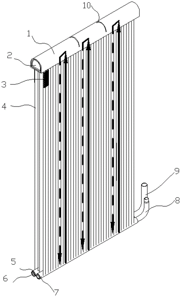
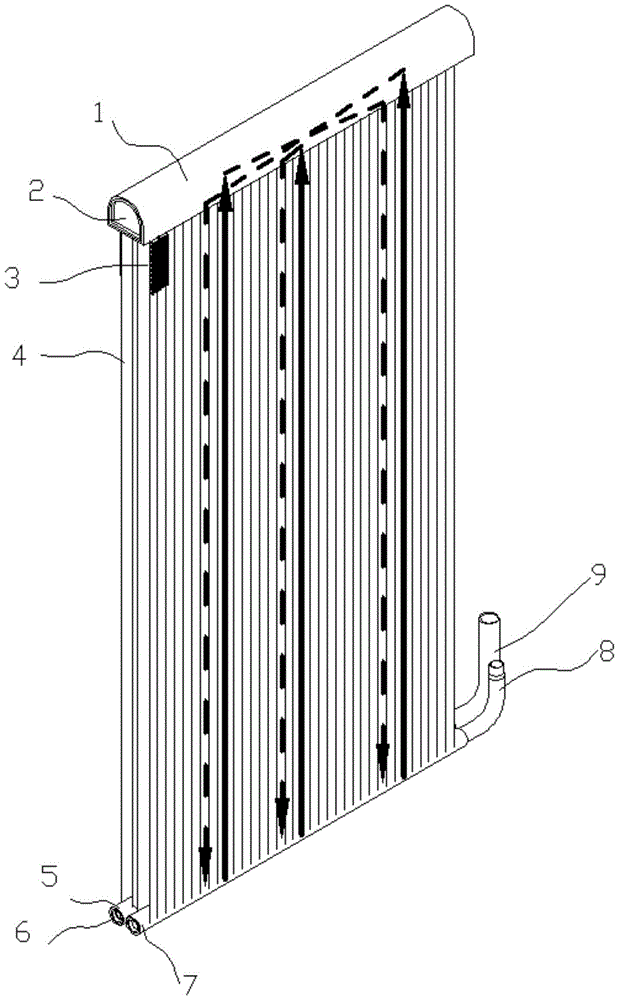
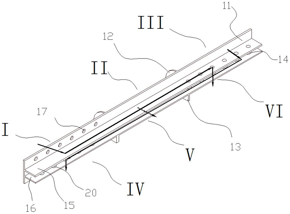
[0036] Such as Figure 2-Figure 5 As shown, a double-row parallel-flow evaporator includes an upper header 1, a first lower header 5, a second lower header 7, and is connected to the upper header 1 and two lower headers. The double-row flat tubes 4 between the tubes 5 and 7, the first lower header 5 communicates with the evaporator input tube 8, and the second lower header 7 communicates with the evaporator output tube 9; The upper header 1 is provided with a diverter plate 11 arranged along its axial direction and divided into two parts, the front header and the rear header, the front header is connected to the front row of flat tubes 4 The second lower header 7 communicates, and the rear header 5 communicates wit...


PUM


Abstract

The invention relates to a double-row parallel flow evaporator comprising an upper collecting pipe, a first lower collecting pipe, a second lower collecting pipe and double rows of flat pipes. The upper collecting pipe is communicated with the two lower collecting pipes through the double rows of flat pipes. The first lower collecting pipe is communicated with an input pipe of the evaporator. The second lower collecting pipe is communicated with an output pipe of the evaporator. A splitter plate is arranged in the upper collecting pipe in the axial direction of the upper collecting pipe and divides the upper collecting pipe into a front collecting area and a rear collecting area. The front collecting area is communicated with the second lower collecting pipe through the front row of flat pipes. The rear collecting area is communicated with the first lower collecting pipe through the rear row of flat pipes. The splitter plate is provided with flow channels allowing refrigerants to pass through, wherein the flow channels are communicated with the left side and the right side of the front collecting area in an intersecting mode and communicated with the left side and the right side of the rear collecting area in an intersecting mode. The structure that the left sides and the right sides are communicated through the front and rear rows of flow channels in the intersecting mode is adopted in the upper collecting pipe, even exchange of the refrigerants on the left and right sides of the evaporator is achieved, the problem that discharged air is not even due to the fact that the amounts of refrigerants are not even is solved, and the comfort of a use environment is improved.

Description

technical field [0001] The invention relates to the field of air conditioners, in particular to an evaporator with double rows of parallel flow. Background technique [0002] The parallel flow heat exchanger has the advantages of small pressure loss on the air side and the refrigerant side, high heat transfer coefficient, light weight, compact structure, and less refrigerant charging, which is conducive to reducing the weight and volume of the air conditioner, achieving The effect of saving energy and reducing consumption has become the most promising type of air conditioner heat exchanger. [0003] attached figure 1 It is a diagram of an existing double-row parallel-flow evaporator. The double-row parallel-flow evaporator includes an upper header, an upper cover, fins, a flat tube, a lower header, a lower cover, and a lower header. Tube two, evaporator input tube, evaporator output tube and separator. After being condensed by the condenser, the refrigerant flows into the...

Claims


Application Information

Patent Timeline
Patent Type & Authority Patents(China)
IPC IPC(8): F25B39/02
CPCF25B39/02F25B2500/09
Inventor 汪先送
Owner GD MIDEA AIR CONDITIONING EQUIP CO LTD
Why Eureka
Try Eureka