Multipoint laser

A laser and multi-point technology, applied in the direction of instruments, simulators, computer control, etc., can solve the problems of extended design cycle, high difficulty, complex optical system, etc., achieve the effect of reducing development and production costs and speeding up the design cycle

Active Publication Date: 2015-09-23
NORTHWEST INSTR SHANGHAI
View PDF4 Cites 1 Cited by
  • Summary
  • Abstract
  • Description
  • Claims
  • Application Information

AI Technical Summary

Problems solved by technology

[0003] Since the existing five-point laser needs to use the optical system to realize its function, the optical system is relatively complicated, and at the same time, the internal structure of the five-point laser needs to be verified and verified by the optical system to ensure the correctness of the five beam paths.
In summary, the existing five-point laser has the disadvantages of high workload and high difficulty in the generation and control of the five beams and the verification of the instrument structure due to the use of an optical system, which increases the development and production costs and prolongs the design time. cycle

Method used


Image

  • Multipoint laser
  • Multipoint laser

Examples


Embodiment 1

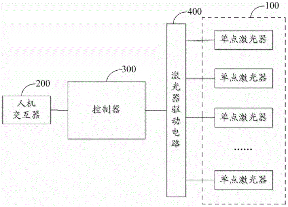
[0024] Embodiment 1 of the present invention discloses a multi-point laser, please refer to figure 1 , the multi-point laser includes N single-point lasers 100 , a human-computer interface 200 , a controller 300 and a laser driving circuit 400 .

[0025] N single-point lasers 100 are used as N light-emitting points, where N is a natural number greater than 1.

[0026] Specifically, the value of N can be determined according to actual application requirements. For example, when four-point lasers are required, N takes a value of 4, and when five-point lasers are required, N takes a specific value of 5. In this embodiment, a five-point laser is taken as an example The present invention will be described in detail.

[0027] The human-computer interaction device 200 is connected with the controller 300 for realizing human-computer interaction.

[0028] Wherein, the human-computer interaction device 200 specifically implements human-computer interaction in the form of buttons.

...

Embodiment 2

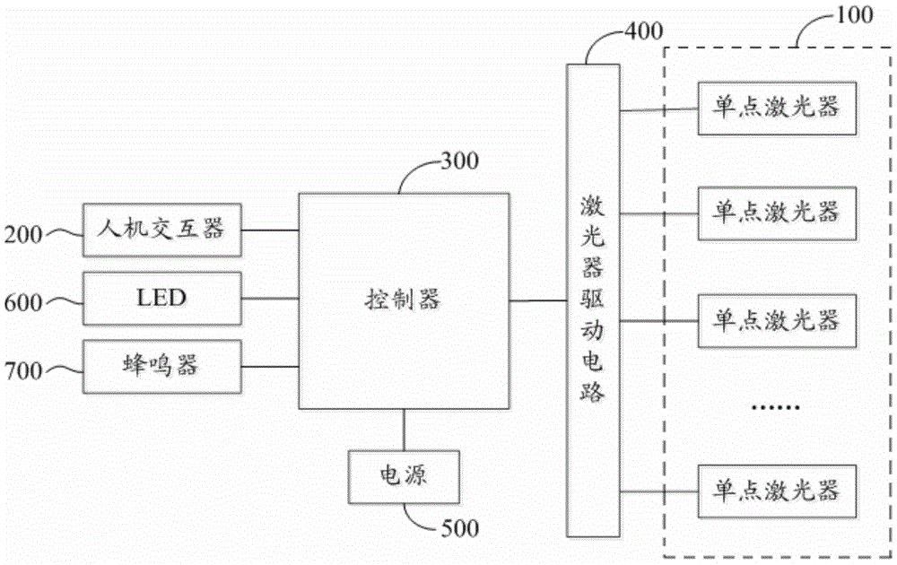
[0041] Embodiment 2 of the present invention perfects and supplements the multi-point laser in Embodiment 1, and discloses another structure of the multi-point laser, such as figure 2 As shown, it includes N single-point lasers 100 , a human-computer interface 200 , a controller 300 and a laser driving circuit 400 , and also includes a power supply 500 , an LED (Light Emitting Diode, light emitting diode) 600 and a buzzer 700 .

[0042] At the same time, the function of the controller 300 has been expanded: the controller 300 is also used to monitor the power of the power battery and the tilt angle of the multi-point laser, and when it is detected that the power of the power battery is not within the preset normal power range, or When the tilt angle of the multi-point laser is not within the preset normal angle range, an alarm signal is generated.


PUM


Abstract

The invention discloses a multipoint laser. The multipoint laser comprises N single-point lasers, a man-machine interaction device, a controller and a laser driving circuit, wherein the N single-point lasers serve as N light emitting points of the multipoint laser, and emission of N laser beams is realized; and the controller controls the on-off states of the N single-point lasers under the indication of the man-machine interaction device, so that the control over switching-on or switching-off of the N laser beams is realized. The laser beams emitted by the N single-point lasers are sent without the help of an optical system formed by a reflector, a prism and the like, and existing N single-point lasers can be adopted to serve as the required N single-point lasers. Thus, the multipoint laser overcomes defects of an existing five-point laser which are caused by that the required five light emitting points are generated by an optical system and the sending of the laser beams is performed by the optical system, and the identification of the optical system is not needed in the instrument, so that the generation and control workload of the plurality of laser beams is lowered, the design period is shortened, and the researching and production costs are reduced.

Description

technical field [0001] The invention belongs to the technical field of industrial control and board card testing, in particular to a multi-point laser. Background technique [0002] At present, the light emission of the five points in the five-point laser is realized through the optical system, that is, the number of light source points is 1, 2 or 3 to generate five points through the optical system composed of reflectors, prisms, etc. luminous points, and the five light beams emitted by the five luminous points are sent through an optical system to realize a five-point laser. [0003] Since the existing five-point laser needs to use the optical system to realize its function, the optical system is relatively complicated, and at the same time, the internal structure of the five-point laser needs to be verified and verified by the optical system to ensure the correctness of the five beam paths. In summary, the existing five-point laser has the disadvantages of high workload ...

Claims


Application Information

Patent Timeline
Patent Type & Authority Applications(China)
IPC IPC(8): G05B19/042
CPCG05B19/042G05B2219/26
Inventor 李明
Owner NORTHWEST INSTR SHANGHAI
Why Eureka
Try Eureka