
igbt drive circuit

A driving circuit and driving signal technology, which is applied in the layout of amplifier protection circuits, electronic switches, electrical components, etc., can solve the problem of failure to realize IGBT turn-on and turn-off, failure to provide IGBT overcurrent, overvoltage, short circuit and other fault protection functions, etc. question

Active Publication Date: 2019-02-19
BEIJING BOE ENERGY TECH +1
View PDF11 Cites 0 Cited by
  • Summary
  • Abstract
  • Description
  • Claims
  • Application Information

AI Technical Summary

Problems solved by technology

[0004] The main purpose of the present invention is to provide a kind of IGBT driving circuit, to solve the problem that the IGBT cannot be turned on and off safely in the prior art, provide electrical isolation between the processor and the IGBT, and cannot provide IGBT overcurrent, overvoltage, Problems with fault protection functions such as short circuits

Method used


Image

  • igbt drive circuit
  • igbt drive circuit
  • igbt drive circuit

Examples


Embodiment Construction

[0054] The following will clearly and completely describe the technical solutions in the embodiments of the present invention with reference to the accompanying drawings in the embodiments of the present invention. Obviously, the described embodiments are only some, not all, embodiments of the present invention. Based on the embodiments of the present invention, all other embodiments obtained by persons of ordinary skill in the art without making creative efforts belong to the protection scope of the present invention.

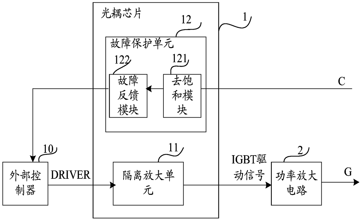
[0055] like figure 1 As shown, the IGBT driving circuit described in the embodiment of the present invention includes an optocoupler chip 1 and a power amplifier circuit 2; the optocoupler chip 1 includes an isolation amplifier unit 11 and a fault protection unit 12; the fault protection unit 12 includes a desaturation Module 121 and fault feedback module 122;

[0056] The isolation and amplification unit 11 is used to photoelectrically isolate and amplify th...


PUM


Abstract

The invention provides an IGBT drive circuit, comprising an optocoupler chip and a power amplifier circuit; the optocoupler chip includes an isolation amplifying unit and a fault protection unit; the fault protection unit includes a desaturation module and a fault feedback module; the desaturation module , which is used to send a warning signal to the fault feedback module when it is detected that the potential of the collector of the IGBT is too high or the potential of the collector of the IGBT changes too fast. The controller sends a fault control signal, so as to control the external drive signal output by the external controller, so that the isolation amplifying unit outputs the IGBT drive signal that controls the IGBT turn-off. The IGBT drive circuit of the present invention uses an optocoupler chip to drive the IGBT, and has the function of detecting faults such as overvoltage, overcurrent, and short circuit of the IGBT.

Description

technical field [0001] The invention relates to the field of IGBT driving, in particular to an IGBT driving circuit. Background technique [0002] IGBT (Insulated Gate Bipolar Transistor, Insulated Gate Bipolar Transistor) is a new type of composite device, which not only has the characteristics of easy driving, but also has the advantages of large tube voltage and current capacity. The operating frequency of the IGBT is in the frequency range of tens of kHz, so it occupies a major application position in the high-frequency and medium-power power electronic equipment. [0003] The IGBT drive circuit is the interface circuit between the IGBT and the DSP (digital signal processing, digital signal processing) chip. Its function is to convert the control signal from the digital signal processor into a drive signal with sufficient power to realize the safe opening of the IGBT. and shutdown, to provide electrical isolation between the processor and the IGBT. In order to correctly...

Claims


Application Information

Patent Timeline
Patent Type & Authority Patents(China)
IPC IPC(8): H03K17/567H03K17/78
CPCH03F3/08H03F3/3069H03K17/163H03K17/168H03K17/603H03F1/52H03K5/08H03K17/78H03F3/21H03F3/26
Inventor 王青猛韩晓艳
Owner BEIJING BOE ENERGY TECH
Features
  • Generate Ideas
  • Intellectual Property
  • Life Sciences
  • Materials
  • Tech Scout
  • Unparalleled Data Quality
  • Higher Quality Content
  • 60% Fewer Hallucinations
Learn More