
Heavy-load beam creel of double-needle-bar warp knitting machine

A double-needle bed warp knitting machine and heavy-duty technology, which is applied in the field of warp knitting machines, can solve problems such as insufficient load, and achieve the effects of increasing load, reducing costs, and improving production efficiency

Inactive Publication Date: 2015-09-30
KARL MAYER CHINA
View PDF6 Cites 0 Cited by
  • Summary
  • Abstract
  • Description
  • Claims
  • Application Information

AI Technical Summary

Problems solved by technology

[0003] In order to overcome the deficiency that the load of the existing warp creel is not strong enough, the present invention provides a heavy-duty warp creel design for a double-needle bed warp knitting machine

Method used


Image

  • Heavy-load beam creel of double-needle-bar warp knitting machine
  • Heavy-load beam creel of double-needle-bar warp knitting machine
  • Heavy-load beam creel of double-needle-bar warp knitting machine

Examples


Embodiment Construction

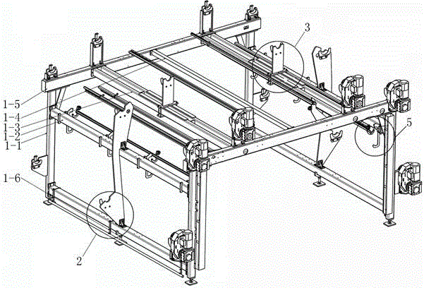
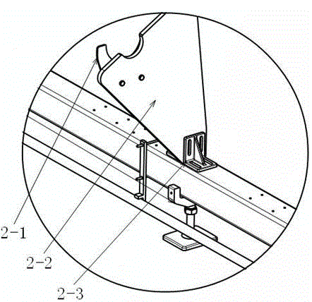
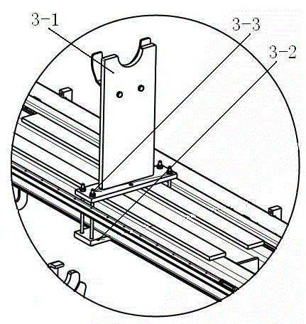
[0020] Such as Figure 1-6 It is a schematic diagram of the structure of the present invention, a heavy-duty warp beam support design for a double-needle bed warp knitting machine, including a warp beam frame 1, a warp beam middle support assembly 2, a warp beam seat 3, a segmented warp beam assembly 4, and a split yarn Rod assembly 5, upper yarn assembly 6, warp beam frame 1 includes four support column assemblies 1-1, four thick transverse support tubes 1-2, two double transverse support tubes 1-3, and one thin transverse support tube 1 -4. Two cross beam assemblies 1-5, middle support angle iron 1-6, the upper ends of the two support column assemblies 1-1 separated by a long distance are connected by cross beam assemblies, and double cross brace pipes are arranged between the cross beam assemblies 1- 3 and the thin cross brace tube 1-4, the thick cross brace tube 1-2 is set between the two support column assemblies 1-1 with a short distance apart, and the middle support angl...


PUM


Abstract

The invention relates to the technical field of warp knitting machines, in particular to a heavy-load beam creel of a double-needle-bar warp knitting machine. The heavy-load beam creel comprises a beam frame, middle beam supporting assemblies, beam bases, a segmented beam assembly, a shed stick assembly and an upper yarn splitting assembly. By adopting segmented beams, additionally arranged horizontal supporting tubes and improved middle beam supports, the loading capacity of the beam creel can be effectively improved, the cost can be lowered, and the production efficiency can be improved; meanwhile, by adopting novel yarn splitting supporting plates and the upper yarn splitting assembly, it is guaranteed that under the condition that the size of a large heavy-load beam is 40 inches, based on the average height of operators, reliability and reasonability of yarn path operation are achieved.

Description

Technical field [0001] The invention relates to the technical field of warp knitting machines, in particular to a heavy-duty warp beam support design for a double-needle bar warp knitting machine. Background technique [0002] With the large demand for spacer fabrics in the market, the output of the original RD6 type machine can no longer meet the requirements of industrialization, which leads to the improvement of the RD6 model. It is most effective to change the matching pan head without changing the main engine. The solution can double the running time of the machine. Some manufacturers have further improved the diameter of the warp beam pan head from 21 inches to 32 inches. However, for a large pan head with a diameter of 40 inches = 1016 mm, the maximum load of the warp beam is increased by six warp beams. Nearly 18 tons, which requires a higher load beam carrier. Summary of the invention [0003] In order to overcome the insufficient load of the existing warp beam support, ...

Claims


Application Information

Patent Timeline
Patent Type & Authority Applications(China)
IPC IPC(8): D04B27/00D04B27/10
Inventor 王超
Owner KARL MAYER CHINA
Learn More