Combustion gas turbine

A gas turbine and gas technology, applied in the direction of gas turbine devices, mechanical equipment, machines/engines, etc., can solve the problems of large axial force, large volume and power, low stage pressure, etc., and achieve the effect of reducing axial force

Inactive Publication Date: 2015-09-30
UNIV OF SHANGHAI FOR SCI & TECH
View PDF7 Cites 5 Cited by
  • Summary
  • Abstract
  • Description
  • Claims
  • Application Information

AI Technical Summary

Problems solved by technology

Due to the relatively low stage pressure, the axial flow compressor needs more stages to complete the boost or work, resulting in a larger overall structure and greater axial force
[0004] Existing axial-flow gas turbines are large in size and power, and most of them are only suitable for high-power conditions

Method used


Image

  • Combustion gas turbine
  • Combustion gas turbine
  • Combustion gas turbine

Examples


Embodiment 1

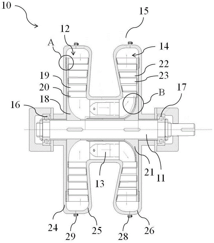
[0027] figure 1 is a sectional view of the gas turbine of the first embodiment.

[0028] Such as figure 1 As shown, the gas turbine 10 includes a main shaft 11 , a radial compressor 12 , a combustor 13 , a centrifugal turbine 14 and a casing 15 .

[0029] The two ends of the main shaft 11 are installed in the bearing 16 and the bearing 17 respectively, and one end of the main shaft 11 is connected to a load (not shown in the figure), and the rotation of the main shaft 11 outputs mechanical work to the load.

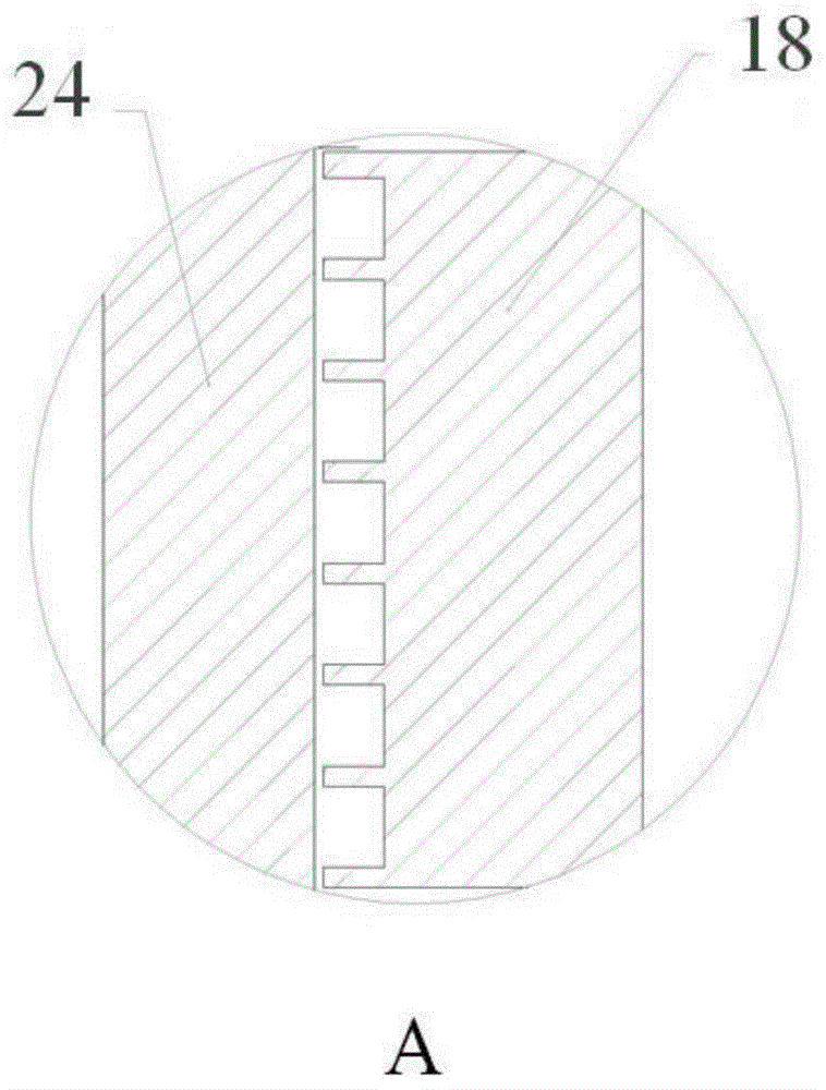
[0030] The centripetal compressor 12 is set on one end of the main shaft 11 and includes a compressor disc 18 , multiple sets of moving blade cascades 19 and multiple sets of static blade cascades 20 . Both the moving blade cascade 19 and the stationary blade cascade 20 are straight blades. The moving blade cascades 19 are installed on the compressor discs 18 respectively. In order to reduce wear and heat, magnetic suspension is used to reduce the friction between the...

Embodiment 2

[0043] Figure 4 is a schematic structural view of the gas turbine of Embodiment 2; and

[0044] Figure 5 is a sectional view of the gas turbine of the second embodiment.

[0045] Such as Figure 4 , 5 As shown, the gas turbine 100 of this embodiment includes a main shaft 101 , a radial compressor 102 , a radial compressor 103 , a combustion chamber 104 , a combustion chamber 105 , a two-way intake centrifugal turbine 106 and a casing 107 .

[0046] The two ends of the main shaft 101 are installed in the bearing 108 and the bearing 109 respectively, and one end of the main shaft 101 is connected to a load (not shown in the figure), and the rotation of the main shaft 101 outputs mechanical work to the load.

[0047] The centripetal compressor 102 and the centripetal compressor 103 are set on both ends of the main shaft 101 respectively. The structural composition of the centripetal compressor is the same as that in Embodiment 1, and both the moving blade cascade and the s...


PUM


Abstract

The invention provides a combustion gas turbine. The combustion gas turbine is characterized by comprising a spindle, radial inflow compressors, combustion chambers, an outward flow turbine and a shell. The spindle outputs mechanical work through rotation, and the spindle is sleeved with the radial inflow compressors; air entering the radial inflow compressors in a radial manner is pressurized through rotation to form high-pressure gas, and then the high-pressure gas is exhausted in the axial direction; the spindle is sleeved with the combustion chambers, and the combustion chambers are communicated with the radial inflow compressors to enable the high-pressure gas to be mixed with fuel to be combusted, and high-temperature high-pressure fuel gas is formed; the spindle is sleeved with the outward flow turbine, and the outward flow turbine is communicated with the combustion chambers; the outward flow turbine is driven by the high-temperature high-pressure fuel gas to rotate so as to drive the spindle to rotate, and then, the high-temperature high-pressure fuel gas is exhausted in the radial direction; and the shell comprises compressor shell bodies, combustion chamber shell bodies and a turbine shell, the compressor shell bodies are provided with air inlets, the turbine shell is provided with an air outlet, and cooling devices are arranged below the combustion chambers and are used for cooling the spindle.

Description

technical field [0001] The invention relates to a gas turbine, in particular to a gas turbine with radial air intake and radial air outlet so as to reduce axial force. Background technique [0002] When the gas turbine is working, it needs to continuously inhale air (i.e., working fluid) from the outside, and then complete the four major processes of compression, combustion heating, expansion and heat release, and continuously convert part of the chemical energy in the fuel into mechanical work. Therefore, gas turbines can be used as ground machinery to provide driving power for power generation, ships, locomotives, pumps, and can also be used to provide power for aviation aircraft and drones. [0003] A gas turbine consists of three major components: a compressor, a combustor, and a turbine. Existing gas turbines mainly fall into two categories: axial flow and radial flow. The axial flow gas turbine is composed of a multistage axial flow compressor and a multistage axial ...

Claims


Application Information

Patent Timeline
Patent Type & Authority Applications(China)
IPC IPC(8): F02C3/09
Inventor 黄典贵谭鑫李银各陈程王竹王乃安林显巧朱文都逄雨萌罗丹陈小刚邵胜博余一凡刘澜一
Owner UNIV OF SHANGHAI FOR SCI & TECH
Why Eureka
Try Eureka