
A thrust chamber collector with flow sharing function

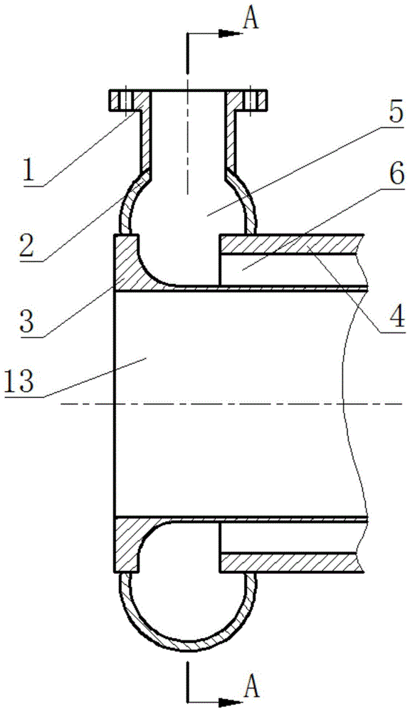
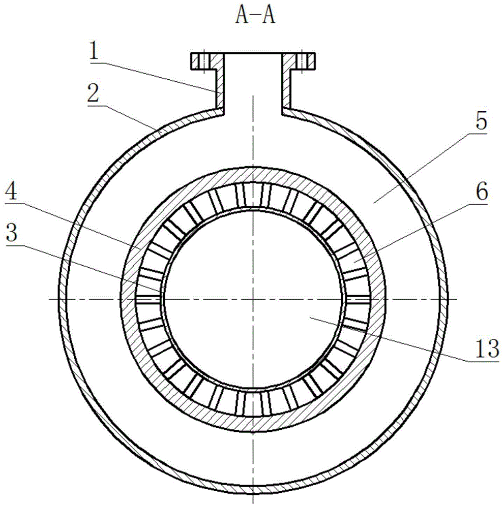
A collector and thrust chamber technology, applied in the field of liquid rocket engine design, can solve problems such as uneven pressure at the outlet of the collector and fluctuations in pressure distribution in the inlet area

Active Publication Date: 2017-02-15
BEIJING AEROSPACE PROPULSION INST
View PDF4 Cites 0 Cited by
  • Summary
  • Abstract
  • Description
  • Claims
  • Application Information

AI Technical Summary

Problems solved by technology

This collector structure has the following disadvantages: (1) The pressure difference formed by the annular flow of the fluid along the collector cavity 5 directly causes the uneven outlet pressure of the collector; (2) The nearly 90-degree right-angle turn at the inlet causes the pressure distribution in the inlet area Fluctuates more violently

Method used


Image

  • A thrust chamber collector with flow sharing function
  • A thrust chamber collector with flow sharing function
  • A thrust chamber collector with flow sharing function

Examples


Embodiment Construction

[0019] The present invention will be described in further detail below in conjunction with the accompanying drawings and specific embodiments.

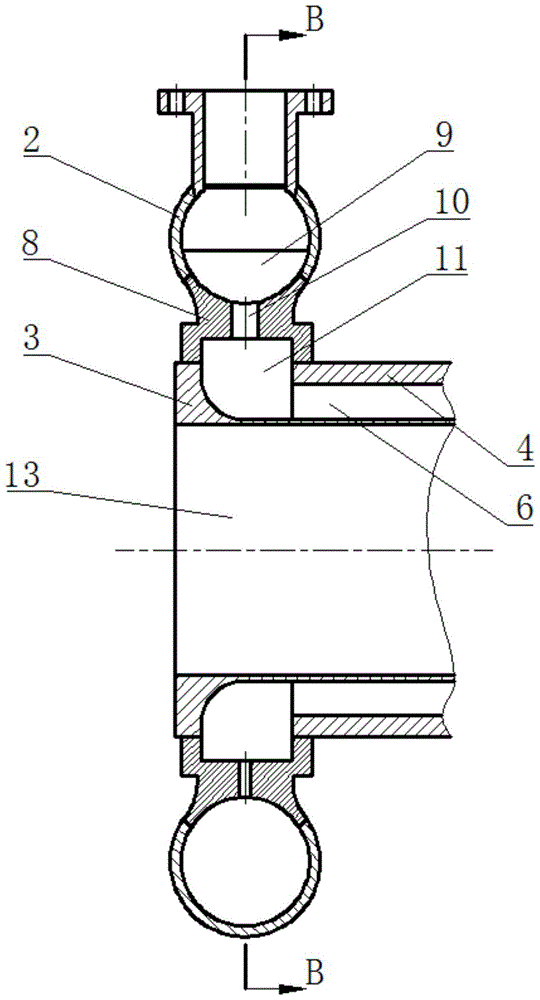
[0020] Such as image 3 and Figure 4 As shown, the collector elbow 2 is an elbow surrounded by pipes with a circular cross-section, and an arc-shaped opening is processed on the inner side of the elbow, and an inlet is processed at any position on the outer circumference of the pipe. An expansion type inlet flange 7 is installed at the inlet, and a "human" shape deflector 12 is welded and fixed at the inlet.

[0021] Weld ring hole seat 8 on the arc opening of the inner side of pipe, described welding ring hole seat 8 is disk shape, and the shape of its section is as image 3 As shown, the outside of the cross-section is arc-shaped, which forms a complete circle with the cross-section of the collector elbow 2, and the inside of the cross-section has a shoulder structure, and the shoulder is fixedly welded to the inner inner wall 3 ...


PUM


Abstract

The invention relates to the liquid rocket propulsion technology, and particularly discloses a thrust chamber collector with a flow uniformizing function. A body shell is composed of an inner wall and an outer wall together. A cylinder formed when the inner wall is closed serves as a combustion chamber. An interlayer between the inner wall and the outer wall forms a cooling passageway. Annular grooves are formed in the inlet and the outlet of the cooling passageway. A bent pipe of the collector is welded and connected to the body shell at the annular groove in the inlet of the cooling passageway. A collector cavity is formed by the bent pipe and the body shell. The opening of the collector cavity is welded and connected to an inlet flange to form a collector inlet. Due to the double-collection-cavity structure, fluid is secondarily uniformized before entering the cooling passageway; by means of a horn-shaped expansion inlet with a reverse-Y-shaped diversion piece, fluid can more stably turn at the collector inlet, pressure fluctuation at the inlet and the two sides is reduced, local pressure loss can be reduced, and the diversion piece can play a role in reinforcing structure supporting.

Description

technical field [0001] The invention belongs to the liquid rocket engine design technology, in particular to a collector for thrust chambers of the liquid rocket engine. Background technique [0002] The cavity of the thrust chamber of the liquid rocket engine is high-temperature and high-pressure gas. In order to avoid ablation damage to the chamber wall, a cooling jacket is installed between the inner wall and the outer wall, and a low-temperature fluid is introduced to cool the chamber wall. The function of the inlet collector is to distribute the fluid delivered by the engine assembly pipeline to each independent channel distributed around the cooling jacket. In order to ensure that the flow distribution of the cooling channel is relatively uniform and to avoid the circumferential uneven temperature of the side wall of the gas, the pressure distribution at the outlet of the collector is required to be as uniform as possible. [0003] Such as figure 1 and figure 2 As ...

Claims


Application Information

Patent Timeline
Patent Type & Authority Patents(China)
IPC IPC(8): F02K9/64
Inventor 周伟杨继东谢恒王晓丽袁宇李晓旭宣智超卢明
Owner BEIJING AEROSPACE PROPULSION INST
Learn More