LED lamp achieving current limiting by means of thermistor

An LED lamp and thermistor technology, applied in the field of lighting, can solve the problems of large drive circuit module volume, increase the overall volume of LED filament lamps, and large difference between LED filament lamps, etc., to achieve temperature protection function and improve user acceptance. , The effect of solving the heat dissipation problem

Inactive Publication Date: 2015-09-30
SHANGHAI DANGOO ELECTRONICS TARDING
View PDF5 Cites 5 Cited by
  • Summary
  • Abstract
  • Description
  • Claims
  • Application Information

AI Technical Summary

Problems solved by technology

[0003] For example, the appearance of LED filament lamps is similar to ordinary incandescent lamps, which makes the user’s acceptance higher. However, due to the relatively lagging technology related to the drive circuit of LED filament lamps, the size of the drive circuit module is relatively large. Traditional LED filament lamps All lamps need to be provided with a plastic shell specially used to place the drive circuit module at the junction between the lamp cap and the bulb, so that the appearance of the entire LED filament lamp is quite different from that of ordinary incandescent lamps, which greatly reduces the acceptance of users. and not convenient for daily use
[0004] In addition, currently, in order to make LED filament lamps realize SCR dimming like incandescent lamps, it is generally necessary to install a dimmable switch power circuit module, but due to the large size of the power circuit module, it cannot be directly placed in the LED filament lamp. In the lamp holder, the overall volume of the LED filament lamp is further increased

Method used


Image

  • LED lamp achieving current limiting by means of thermistor
  • LED lamp achieving current limiting by means of thermistor

Examples


Embodiment Construction

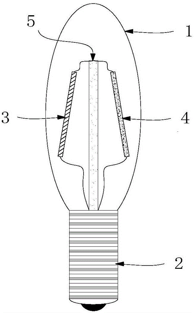
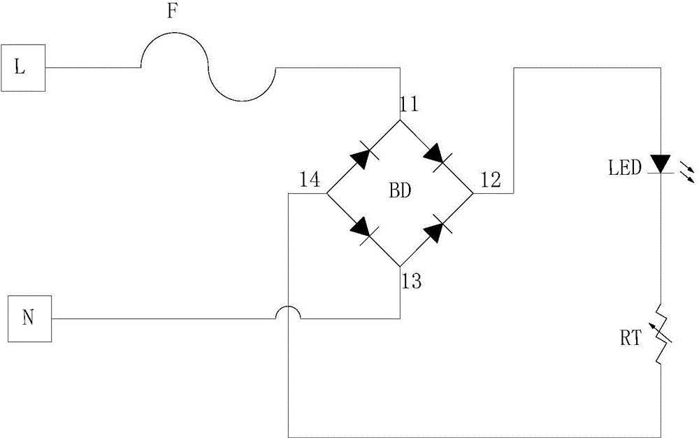
[0028] The LED lamp using the thermistor current limiting provided in the embodiment of the present invention can be applied to filament lamp products, mainly by using the thermistor in series with the LED filament to limit the current, and also by connecting the thyristor dimmer in series Then realize the function of LED filament dimming; because the thermistor connected in series with the LED filament is a miniaturized positive temperature coefficient thermistor, its resistance increases when the temperature rises to reduce the current in the circuit, thereby reducing Power, to keep the power of the LED filament within the rated range, that is, the positive temperature coefficient thermistor is used to limit the current flowing through the LED filament within the rated current range (to achieve a constant current effect), because the current-limiting thermistor is in A certain amount of power is lost during work, and as the current on the LED filament increases, the power los...


PUM


Abstract

The invention provides an LED lamp achieving current limiting by means of a thermistor, and relates to the technical field of lighting. By placing the current limiting thermistor of which the power consumption is big in a bulb shell, the heat dissipation problem is solved, and the temperature protection function is achieved; meanwhile, rectifying equipment is embedded in a lamp holder arranged on the LED lamp, and therefore the size of the LED lamp is smaller; the thermistor is connected between LED lamp filaments and a power source in series, the currents flowing through the LED lamp filaments are limited within a rated power range, and the effect of constant current of the LED lamp filaments is achieved. According to the LED lamp, the circuit is simple, the overall appearance of the LED lamp is more similar to the appearance of an incandescent lamp, therefore, the user acceptability is effectively improved, and application and popularization are convenient.

Description

technical field [0001] The invention relates to the technical field of lighting, in particular to an LED lamp using a thermistor to limit current. Background technique [0002] At present, the new generation of electric light source LED lights are widely used in people's daily life due to their advantages such as high electro-optical conversion rate, long life, low cost and environmental protection. LED technology has developed rapidly and derived many types of lighting device. [0003] For example, the appearance of LED filament lamps is similar to ordinary incandescent lamps, which makes the user’s acceptance higher. However, due to the relatively lagging technology related to the drive circuit of LED filament lamps, the size of the drive circuit module is relatively large. Traditional LED filament lamps All lamps need to be provided with a plastic shell specially used to place the drive circuit module at the junction between the lamp cap and the bulb, so that the appeara...

Claims


Application Information

Patent Timeline
Patent Type & Authority Applications(China)
IPC IPC(8): F21S2/00F21V23/02F21V23/00F21V3/04F21Y101/02
CPCF21V23/02F21V3/061F21V23/003
Inventor 朱明星
Owner SHANGHAI DANGOO ELECTRONICS TARDING
Why Eureka
Try Eureka