
Line scanning camera imaging method for object with variable thickness

A technology of line scan camera and thickness change, applied in the direction of measuring device, material analysis through optical means, instrument, etc., can solve the problems of complex structure, lower system imaging precision, few patents for adjusting imaging distance change, etc., and achieve increase The effect of applicability

Active Publication Date: 2015-09-30
BAOSHAN IRON & STEEL CO LTD
View PDF7 Cites 10 Cited by
  • Summary
  • Abstract
  • Description
  • Claims
  • Application Information

AI Technical Summary

Problems solved by technology

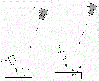
To ensure that the detection optical path remains unchanged for the movement of imaging components, it is necessary to move the light source 1 and camera 2 for imaging as a whole. Frequent and slight movements during the application process complicate the system design, and equipment wear will also reduce the imaging accuracy of the system
[0004] According to the patent literature search, there are many patents related to line scan camera imaging and camera calibration, but there are few patents specific to the adjustment of imaging with the change of imaging distance
Chinese patent 200710046375.1 discloses a strip steel follow-up imaging visual inspection method, which is a method of synchronously adjusting the light source and camera imaging during the coiling position of the strip steel increases with the coil diameter, the method needs to move the camera and light source at the same time , and it is necessary to monitor the diameter change of the coil, the method has a complex structure

Method used


Image

  • Line scanning camera imaging method for object with variable thickness
  • Line scanning camera imaging method for object with variable thickness
  • Line scanning camera imaging method for object with variable thickness

Examples


Embodiment Construction

[0038] The present invention will be further described below in conjunction with the accompanying drawings and specific embodiments.

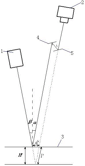
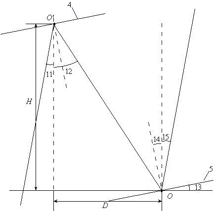
[0039] A line scan camera imaging method for object thickness changes. The camera 2 and the light source 1 form the imaging optical path of the detection system at a set angle, and a plane mirror group is arranged on the reflected optical path of the object to be imaged. The light is emitted from the light source 1 and passes through the imaging path. After surface 3 is reflected, enter camera 2 imaging after plane mirror group 4,5 again; Said plane mirror group comprises first plane mirror 4 and second plane mirror 5, and first plane mirror 4 and second plane mirror 5 reflection surfaces are opposite and parallel, first Plane mirror 4 and the second plane mirror 5 are elongated, and the first plane mirror 4 and the second plane mirror 5 are rotated with the length direction rotation axis of crossing width midpoint respectively, and the distance...


PUM


Abstract

The invention relates to the machine vision detection and measurement field and provides a line scanning camera imaging method for an object with variable thickness. A camera (2) and a light source (1) form an imaging light path of a detection system in a set angle, a plane mirror set is arranged on a reflection light path of light rays of an imaged object, light rays are emitted from a light source and then enter the camera to be imaged through the plane mirror set after being reflected by an imaging surface (3); the plane mirror set comprises a first plane mirror (4) and a second plane mirror (5), the reflection surfaces of the first plane mirror and the second plane mirror are opposite and parallel, the first plane mirror and the second plane mirror rotate around rotating shafts passing through the center points of the width in a length direction respectively, and a distance between two plane mirrors can be adjusted; when the surface height of the imaged object is changed, the distance and the angle between two plane mirrors are adjusted to maintain the positions of the original imaging light source and the camera to be unchanged, and imaging can be realized effectively; and the method can be applied to the surface detection system for steel and iron plate blanks, copper tapes and the like, which have great vibration in thickness.

Description

technical field [0001] The invention relates to the field of machine vision detection and measurement, in particular to a line scan camera imaging method for object thickness variation. Background technique [0002] The machine vision detection and measurement technology based on CCD imaging uses images as the detection medium, has the advantages of fast detection speed, high precision, and good consistency of detection standards, and is widely used in socialized mass production processes. Among them, the strip surface quality online detection technology based on the line scan camera, which can save the intuitive image results of surface defects and can generate textual and quantitative quality reports, has become an important auxiliary means of quality control. [0003] In the strip steel production industry, the machine vision surface quality inspection system has also been widely used, which fully reflects the advantages of the technology's adaptability to high-speed ...

Claims


Application Information

Patent Timeline
Patent Type & Authority Applications(China)
IPC IPC(8): G01N21/88G01N21/01
Inventor 王康健杨水山宗德祥何永辉彭铁根石桂芬梁爽
Owner BAOSHAN IRON & STEEL CO LTD
Learn More