
Substrate processing apparatus, nozzle and substrate processing method

A substrate processing device and substrate technology, which is applied to the surface coating device, electrical components, semiconductor/solid device manufacturing, etc., can solve the problems of disturbing the liquid surface, inability to supply new liquid uniformly, and processing substrates, etc.

Active Publication Date: 2015-09-30
DAINIPPON SCREEN MTG CO LTD
View PDF7 Cites 7 Cited by
  • Summary
  • Abstract
  • Description
  • Claims
  • Application Information

AI Technical Summary

Problems solved by technology

However, in these cases, the liquid level of the new liquid extending in the width direction of the substrate may be disturbed by the air.
As a result, the new liquid cannot be supplied uniformly, so there is a possibility that the substrate cannot be uniformly processed with the new liquid.

Method used


Image

  • Substrate processing apparatus, nozzle and substrate processing method
  • Substrate processing apparatus, nozzle and substrate processing method
  • Substrate processing apparatus, nozzle and substrate processing method

Examples


no. 1 Embodiment approach

[0106]

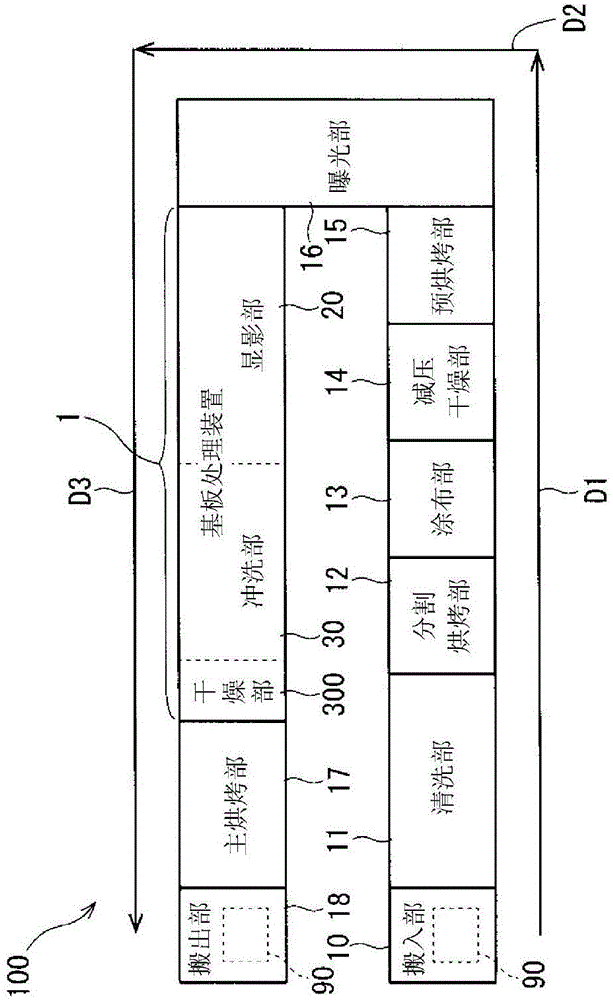
[0107] figure 1 It is a schematic plan view showing a substrate processing system 100 including the substrate processing apparatus 1 .

[0108] The substrate processing system 100 processes a square glass substrate (hereinafter simply referred to as a substrate) 90 for manufacturing a screen panel of a liquid crystal display device.

[0109] The substrate processing system 100 includes a loading unit 10 , a cleaning unit 11 , a divide bake unit 12 , a coating unit 13 , a reduced-pressure drying unit 14 , and a pre-bake unit 15 . The carrying-in unit 10 is a part that receives a substrate 90 to be processed in the substrate processing system 100 . The cleaning unit 11 cleans and cleans the substrate 90 carried in by the carrying-in unit 10 . The divided baking unit 12 dries the substrate 90 to which the cleaning liquid adhered in the cleaning unit 11 .

[0110] The coating unit 13 coats a processing liquid (here, a resist) on the surface of the substrate 90 dried ...

no. 2 Embodiment approach

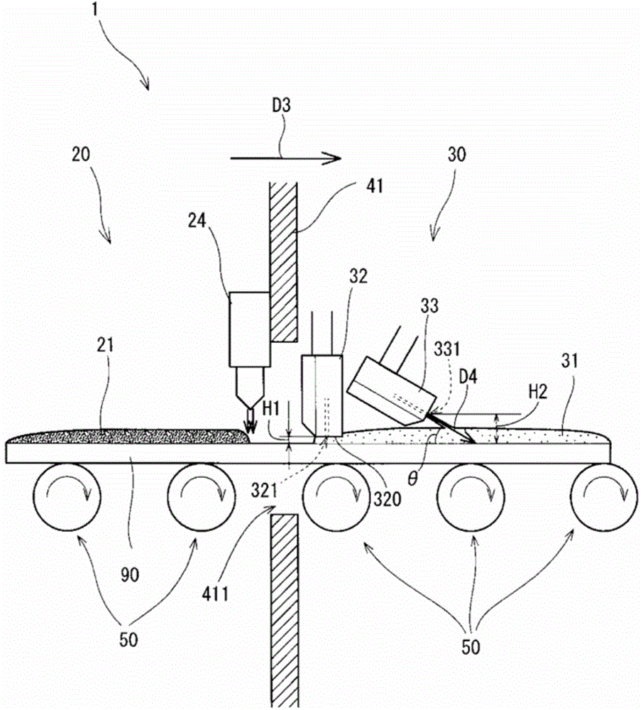
[0150] The substrate processing apparatus 1 of the above-described embodiment includes two nozzles (a rinse coating nozzle 32 and a liquid knife nozzle 33 ) in the rinse unit 30 . However, it is also conceivable to configure these two nozzles with one nozzle. In addition, in the following description, members having the same functions as those already described are assigned the same symbols or symbols with alphabets (alphabets) added thereto, and detailed explanations may be omitted.

[0151] Image 6 It is an enlarged schematic side view showing a boundary portion between the developing unit 20 and the rinse unit 30A in the substrate processing apparatus 1A according to the second embodiment. Such as Image 6 As shown, the substrate processing apparatus 1A is different from the substrate processing apparatus 1 in that a single nozzle 36 is provided instead of the rinse lamination nozzle 32 and the liquid knife nozzle 33 .

[0152] The nozzle 36 has a first discharge part 3...


PUM


Abstract

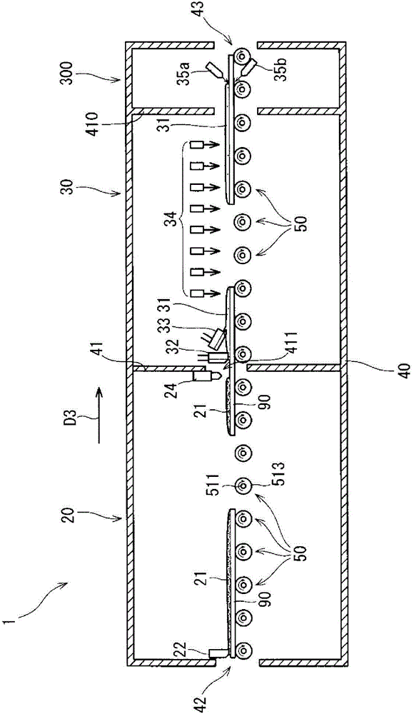
The invention provides a substrate processing apparatus, a nozzle and a substrate processing method, and provides the technology that a substrate where a pre-processing fluid is adhered is uniformly processed through a processing fluid. The substrate processing apparatus conveys a substrate where a developing solution is adhered from the upstream side of a conveying direction (the third direction) to a downstream side through a plurality of conveying rollers. An air nozzle supplies curtain type air to the surface of the substrate conveyed to the downstream side, so as to remove the developing solution accumulated on the substrate. A washing nozzle with a fluid is disposed at the downstream side of the air nozzle so as to form a vent, below the lower surface, used for spraying washing fluid. The washing fluid sprayed from the washing nozzle with the fluid and towards the substrate contacts with the substrate and the lower surface, and spreads in gaps between the substrate and the lower surface. A liquid cut nozzle is disposed at the downstream side of the washing nozzle with the fluid, and can spay film type washing fluid to the substrate.

Description

technical field [0001] The present invention relates to a technique for replacing and treating a substrate to which a pretreatment liquid adheres with another treatment liquid. Background technique [0002] Conventionally, there has also been proposed a technique in which a substrate to which another processing liquid adheres is replaced with a new processing liquid to process the substrate (for example, Patent Document 1). [0003] The residual liquid removal device disclosed in Patent Document 1 has a structure in which the stripping liquid (old liquid) supplied to the glass substrate is replaced with a new stripping liquid in resist stripping equipment for manufacturing liquid crystal panels. liquid (new liquid). More specifically, the residual liquid removal device blows curtain-shaped air from the first liquid removal member toward the moving glass substrate to remove the stripping liquid (old liquid). Then, a new stripping liquid (new liquid) is supplied to the glass...

Claims


Application Information

Patent Timeline
Patent Type & Authority Applications(China)
IPC IPC(8): H01L21/67B05C11/00
Inventor 山下永二富藤幸雄羽方满之
Owner DAINIPPON SCREEN MTG CO LTD
Learn More