Reactive compensation device for 10 kV transmission circuit

A compensation device and circuit technology, applied in reactive power compensation, reactive power adjustment/elimination/compensation, etc., can solve problems such as overvoltage, failure to track load changes in time, and reactive power demand fluctuations

Inactive Publication Date: 2015-09-30
LINHUAN COKING
View PDF4 Cites 1 Cited by
  • Summary
  • Abstract
  • Description
  • Claims
  • Application Information

AI Technical Summary

Problems solved by technology

Among them, the busbar of section III is closed with the busbar of section I or section II through the bus tie switch according to the actual situation. After testing in the incoming cabinets of sections I and II of 10kV, it is found that the load characteristics are stable, but because the busbar of section III is not fixed. Section II bus runs in parallel, which leads to large fluctuations in reactive power demand on Section I or Section II lines, and a dynamic reactive power compensation device needs to be installed
Although the fixed capacitor bank compensation with a reactance rate of 6% and 2.4Mvar has been installed, it is obvious that the compensation of the fixed capacitor bank cannot track the change of the load in time. Parallel resonance phenomenon in power system

Method used


Image

  • Reactive compensation device for 10 kV transmission circuit
  • Reactive compensation device for 10 kV transmission circuit
  • Reactive compensation device for 10 kV transmission circuit

Examples


Embodiment Construction

[0013] In order to deepen the understanding of the present invention, the present invention will be further described below in conjunction with the embodiments and accompanying drawings. The embodiments are only used to explain the present invention and do not constitute a limitation to the protection scope of the present invention.

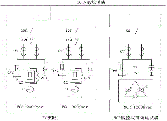
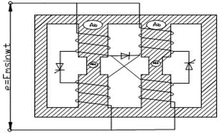
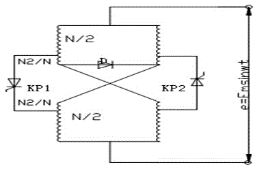
[0014] Attached below Figure 1-3 Detailed description of the preferred implementation of the present invention: a 10KV transmission circuit reactive power compensation device, the 10KV transmission circuit reactive power compensation device includes three-phase identical thyristor valves and their trigger plates and supporting trigger optical fibers, the thyristor valves are connected to magnetic The control box and the magnetic control box are externally connected to an RC circuit and a high potential trigger board. The power and working voltage of the thyristor element of the magnetron reactor are only about 1% of the rated power and voltage o...


PUM


Abstract

The invention discloses a reactive compensation device for a 10 kV transmission circuit and relates to the technical field of electrical power systems. The reactive compensation device comprises a thyristor valve with three identical phases, a triggering circuit board of the thyristor valve and a matched trigger optical fiber, wherein the thyristor valve is connected with a magnetic control box, and an RC circuit and a high-potential trigger board are externally connected to the magnetic control box. The power factor can be increased by means of the reactive compensation device for the 10 kV transmission circuit, the utilization rate of an electrical power system and equipment for electricity enterprises can be increased, electric energy loss can be reduced, the electricity use quality is improved, and the reactive compensation device is an important technological measure for power saving and has good social benefits in the aspect of energy saving.

Description

technical field [0001] The invention relates to the technical field of power systems, in particular to a reactive power compensation device for a 10KV transmission circuit. Background technique [0002] The 10kV gas purification high distribution room has 10kV Ⅰ, Ⅱ, Ⅲ sections of busbars to supply the required electric energy for the motor load. The main loads include high-voltage motors such as water pumps, fans, and air compressors. Among them, the busbar of section III is closed with the busbar of section I or section II through the bus tie switch according to the actual situation. After testing in the 10kV section I and section II incoming cabinets, it is found that the load characteristics are stable, but because the busbar of section III is not fixed with the section I or section Section II buses run in parallel, which leads to large fluctuations in reactive power demand on Section I or Section II lines, and a dynamic reactive power compensation device needs to be inst...

Claims


Application Information

Patent Timeline
IPC IPC(8): H02J3/18
CPCY02E40/30
Inventor 邵瑞张凯王厚元
Owner LINHUAN COKING
Why Eureka
Try Eureka