Wireless power transmission device and toy rail car

A technology of wireless power transmission and voltage, applied in circuit devices, battery circuit devices, electric vehicles, etc., can solve the problems of low current frequency, poor efficiency, unstable wireless transmission performance, etc., to achieve high voltage and power, high transmission efficiency Effect

Inactive Publication Date: 2015-09-30
TIANJIN UNIVERSITY OF TECHNOLOGY
View PDF7 Cites 5 Cited by
  • Summary
  • Abstract
  • Description
  • Claims
  • Application Information

AI Technical Summary

Problems solved by technology

[0006] In the existing technology, 220V, 50Hz alternating current is directly used as the induction current. This kind of current has

Method used


Image

  • Wireless power transmission device and toy rail car
  • Wireless power transmission device and toy rail car
  • Wireless power transmission device and toy rail car

Examples


Embodiment Construction

[0046] The present invention will be further described in detail below in conjunction with the accompanying drawings, so that those skilled in the art can implement it with reference to the description.

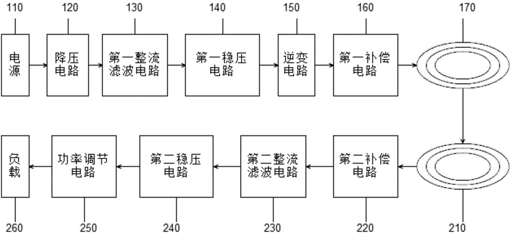
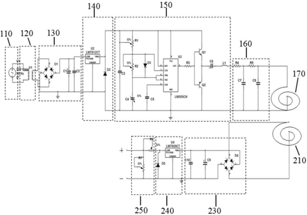
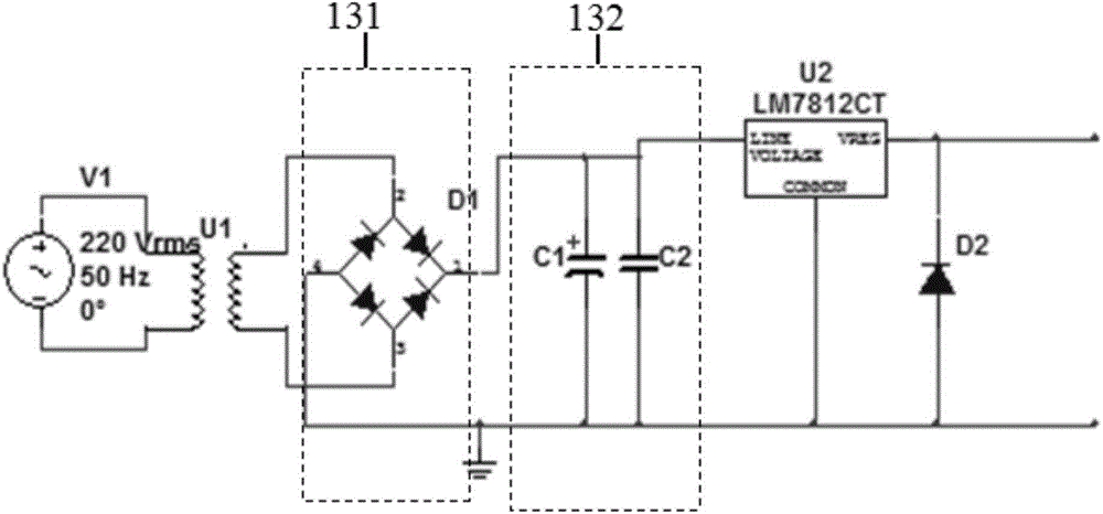
[0047] Such as figure 1 , figure 2 , as shown, the present invention provides a wireless power transmission device, including a wireless power transmitting circuit 100 and a wireless power receiving circuit 200, wherein the wireless power transmitting circuit 100 includes a power supply 110, a step-down circuit 120, a first rectifying circuit connected in sequence Filter circuit 130 , first voltage stabilizing circuit 140 , inverter circuit 150 , first compensation circuit 160 and power transmission coil 170 .

[0048] The wireless power receiving circuit 200 includes a receiving coil 210 , a second compensation circuit 220 , a second rectifying and filtering circuit 230 , a second voltage stabilizing circuit 240 , a power regulating circuit 250 and a load 260 connected in ...


PUM


Abstract

The invention discloses a wireless power transmission device. The wireless power transmission device comprises a wireless power emission circuit and a wireless power receiving circuit, wherein the wireless power emission circuit comprises a power supply, a voltage reduction circuit, a first rectifier and filter circuit, a first voltage stabilizing circuit, an inverter circuit, a first compensating circuit and a power transmission coil which are connected sequentially; the wireless power receiving circuit comprises a receiving coil, a second compensating circuit, a second rectifier and filter circuit, a second voltage stabilizing circuit and a power adjusting circuit which are connected sequentially. The power transmission coil and the receiving coil adopt electromagnetic induction manners, so that the receiving coil induces change of a magnetic field of an emission coil to generate induced current. With the adoption of the wireless power transmission device, non-contact power transmission is realized, the power transmission process is kept stable, the transmission efficiency is high, and voltage and power at the load end are adjustable. The invention further provides a toy rail car capable of realizing wireless charging.

Description

technical field [0001] The invention relates to the field of wireless charging, and more specifically relates to wireless power supply for toy racing cars. Background technique [0002] Wireless power transmission technology began in 1889 with the research of the Croatian-American physicist Tesla. He once imagined using the earth as the inner conductor and the earth's ionosphere as the outer conductor, using electromagnetic waves around the earth's surface to transmit electric energy. In the experimental system he built, a huge coil was used to try to transmit electric energy to all parts of the world. Some isolated houses provide lighting. However, due to the huge cost of the experiment, it did not solve the key issues such as the directional transmission of electric energy, so it did not reach the practical stage. [0003] Over the years, scientists at home and abroad have persistently carried out a lot of exploration and research work in wireless power transmission tech...

Claims


Application Information

Patent Timeline
IPC IPC(8): H02J17/00H02J7/00
Inventor 周海波王桂莲杨超赵玉成王收军朱培浩张亮
Owner TIANJIN UNIVERSITY OF TECHNOLOGY
Why Eureka
Try Eureka