Fire extinguisher

A fire extinguisher and fire extinguishing agent technology, which is applied in fire rescue and other directions, can solve the problems of many parts, increase production cost, and affect fire extinguishing effect, and achieve the effect of reducing production cost, ensuring fire extinguishing effect, and simple manufacturing process

Inactive Publication Date: 2015-10-07
ANHUI TIANYUAN FIRE PROTECTION TECH
View PDF4 Cites 3 Cited by
  • Summary
  • Abstract
  • Description
  • Claims
  • Application Information

AI Technical Summary

Problems solved by technology

In the actual use of the fire extinguisher, since the steel cylinder 1 encapsulating carbon dioxide gas is placed upside down in the fire extinguisher bottle 2, the needle 3 for piercing the seal of the steel cylinder 1 and the spring seat 4' for installing the needle 3 need to be located at the seal of the steel cylinder 1. When in use, when the puncture needle 3 pierces the seal of the steel cylinder 1, the carbon dioxide gas in the steel cylinder 1 will quickly leak from the air hole 5 of the spring seat 4 into the fire extinguisher bottle body 2 and mix the carbon dioxide gas in the fire extinguisher bottle body 2 Fire extinguishing agent, at this time, the pressure in the fire extinguisher bottle body 2 is rapidly increased and the fire extinguishing agent is driven to spray upward from the bottom of the installation pipe 6 for installing the spring seat 4 toward the nozzle 7.1 of the valve body 7, but the fire extinguisher bottle body 2 quickly While pressurizing, the pressure in the fire extinguisher bottle body 2 is likely to be greater than the pressure of the steel cylinder 1, and the air hole 5 of the spring seat 4 is located below the seal of the steel cylinder 1 and is closer to the bottom of the installation pipe 6, so that the fire extinguishing agent has It may enter from the air hole 5 of the spring seat 4, thereby affecting the release of the carbon dioxide gas in the steel cylinder 1 from the air hole 5, so after this type of fire extinguisher is extinguished, there is still about 30% of the fire extinguishing agent in the fire extinguisher body 2 , the fire extinguishing agent is not fully utilized, which affects the fire extinguishing effect
In addition, the manufacturing process of the internal structure of this type of fire extinguisher is relatively complicated, and there are many parts, which increases the production cost to a certain extent.

Method used


Image

  • Fire extinguisher
  • Fire extinguisher

Examples


Embodiment Construction

[0017] The present invention will be further described below in conjunction with the accompanying drawings and specific embodiments.

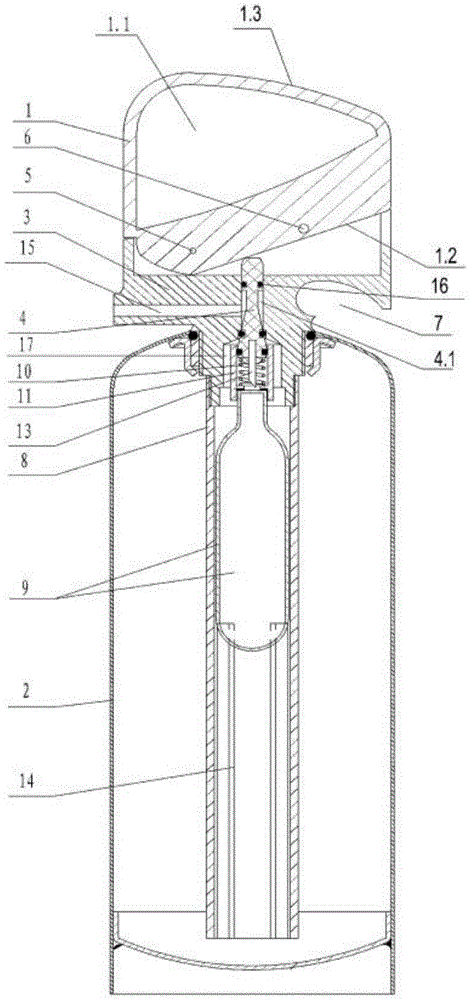
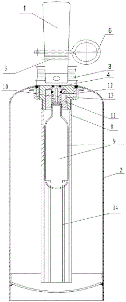
[0018] Such as Figure 1 to Figure 2 As shown, the fire extinguisher of the present invention comprises a bottle body 2 with fire extinguishing agent inside, a handle 1, a valve body 3, a suction pipe 8, a steel cylinder 9 that is used to encapsulate carbon dioxide gas and is located in the suction pipe 8, and the outer wall of the steel cylinder 9 There is a gap between the inner wall of the bottle body 2.

[0019] The upper end of the suction pipe 8 is mounted on the lower end of the valve body 3 by screwing, and there is a distance between the bottom of the suction pipe 8 and the bottom of the bottle body 2, that is to say, the suction pipe 8 is suspended in the bottle body 2 .

[0020] The valve body 3 is installed on the bottle mouth of the bottle body 2 by means of screw connection (that is, threaded connection), and the upper part of t...


PUM


Abstract

The invention provides a fire extinguisher. The fire extinguisher comprises a bottle body (2), a handle (1), a valve body (3), a suction pipe (8) and a steel bottle (9), wherein the valve body (3) is internally provided with a valve rod (4) and a spring seat (11), and a resetting spring (10) is arranged in an inner cavity of the spring seat (11); an airflow channel (12) is formed in one side of the spring seat (11), one end of the airflow channel (12) is communicated with the inner cavity of the spring seat (11) and the other end of the airflow channel (12) extends to the outer side wall of the valve body (3) and is communicated with the inner cavity of the bottle body (2); the steel bottle (9) is arranged in the suction pipe (8) in a manner that the bottle bottom is arranged downwards and the bottle opening is arranged upwards; the lower end of the valve rod (4) is provided with a piercing needle (13) for piercing a sealing opening of the steel bottle (9); the steel seat (11) is arranged on the bottleneck of the steel bottle (9); and the resetting spring (10) sleeves the piercing needle (13). By virtue of the fire extinguisher, the utilization rate of a fire extinguishing agent can be improved, the utilization rate of the fire extinguishing agent is improved, the manufacturing process is simple, few parts are needed and the production cost is relatively low.

Description

Technical field: [0001] The invention relates to a fire fighting equipment, specifically a high-pressure fire extinguisher. Background technique: [0002] The amount of fire extinguishing agent sprayed in the fire extinguisher is one of the key factors for the full utilization of the fire extinguishing agent. and figure 1 It is a partial cross-sectional structural schematic diagram of a relatively common fire extinguisher. In the actual use of the fire extinguisher, since the steel cylinder 1 encapsulating carbon dioxide gas is placed upside down in the fire extinguisher bottle 2, the needle 3 for piercing the seal of the steel cylinder 1 and the spring seat 4' for installing the needle 3 need to be located at the seal of the steel cylinder 1. When in use, when the puncture needle 3 pierces the seal of the steel cylinder 1, the carbon dioxide gas in the steel cylinder 1 will quickly leak from the air hole 5 of the spring seat 4 into the fire extinguisher bottle body 2 and ...

Claims


Application Information

Patent Timeline
Patent Type & Authority Applications(China)
IPC IPC(8): A62C13/00A62C13/76
CPCA62C13/00A62C13/76
Inventor 何越潘来东
Owner ANHUI TIANYUAN FIRE PROTECTION TECH
Why Eureka
Try Eureka