Ultra-low emission absorption tower
An absorption tower and ultra-low technology, applied in the field of absorption towers, can solve the problems of inability to meet ultra-low emission requirements, excessive dust emission concentration, and low dust removal efficiency of absorption towers, so as to increase spray coverage and reduce maintenance and replacement. Cost and ease of installation
- Summary
- Abstract
- Description
- Claims
- Application Information
AI Technical Summary
Problems solved by technology
Method used
Image

Examples
Embodiment 1
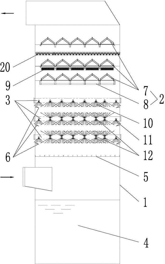
[0035] Embodiment 1 of the present invention: as figure 1As shown, an ultra-low emission absorption tower includes an absorption tower body 1, a mist eliminator 2, a spray layer 3 and a slurry pool 4, the slurry pool 4 is located at the bottom of the absorption tower body 1, and the mist eliminator 2 is located at the bottom of the absorption tower body 1. In the upper part of the absorption tower body 1, the spray layer 3 is set under the demister 2, and the bottom of the spray layer 3 is provided with a slurry distribution plate 5; the bottom of each spray layer 3 is equipped with a slurry guide Ring 6; mist eliminator 2 is composed of three sets of roof type mist eliminators 7 and one set of pipe type mist eliminators 8, the pipe type mist eliminators 8 are located below the bottom of the roof type A condensation system 9 is provided between the mist eliminator 7 and the middle roof ridge type mist eliminator 7 . The spray layer 3 is more than 2 layers, and the uppermost s...
Embodiment 2
[0040] Embodiment 2 of the present invention: as figure 1 As shown, an ultra-low emission absorption tower includes an absorption tower body 1, a mist eliminator 2, a spray layer 3 and a slurry pool 4, the slurry pool 4 is located at the bottom of the absorption tower body 1, and the mist eliminator 2 is located at the bottom of the absorption tower body 1. In the upper part of the absorption tower body 1, the spray layer 3 is set under the demister 2, and the bottom of the spray layer 3 is provided with a slurry distribution plate 5; the bottom of each spray layer 3 is equipped with a slurry guide Ring 6; mist eliminator 2 is composed of three sets of roof type mist eliminators 7 and one set of pipe type mist eliminators 8, the pipe type mist eliminators 8 are located below the bottom of the roof type A condensation system 9 is provided between the mist eliminator 7 and the middle roof ridge type mist eliminator 7 . The spray layer 3 is more than 2 layers, and the uppermost ...
Embodiment 3
[0045] Embodiment 3 of the present invention: as figure 1 As shown, an ultra-low emission absorption tower includes an absorption tower body 1, a mist eliminator 2, a spray layer 3 and a slurry pool 4, the slurry pool 4 is located at the bottom of the absorption tower body 1, and the mist eliminator 2 is located at the bottom of the absorption tower body 1. In the upper part of the absorption tower body 1, the spray layer 3 is set under the demister 2, and the bottom of the spray layer 3 is provided with a slurry distribution plate 5; the bottom of each spray layer 3 is equipped with a slurry guide Ring 6; mist eliminator 2 is composed of three sets of roof type mist eliminators 7 and one set of pipe type mist eliminators 8, the pipe type mist eliminators 8 are located below the bottom of the roof type A condensation system 9 is provided between the mist eliminator 7 and the middle roof ridge type mist eliminator 7 . The spray layer 3 is more than 2 layers, and the uppermost ...
PUM
 Abstract
Description
Claims
Application Information