Thermoplastic plastic powder spray fusing device

A thermoplastic and powder technology, applied in the field of thermoplastic powder spray melting device, can solve the problems of affecting the mechanical properties and apparent quality of materials, unable to adapt to the coating of large panels, uneven powder particle division, etc., to avoid thermal problems. Insufficient melting, shortened spraying time, reasonable structure effect

Inactive Publication Date: 2020-11-06
蒙城县虹升塑粉有限公司
View PDF14 Cites 3 Cited by
  • Summary
  • Abstract
  • Description
  • Claims
  • Application Information

AI Technical Summary

Problems solved by technology

The thermoplastic powder melting device solves the problem that the plastic powder will be deposited at the bottom of the composite raw material mixture due to gravity, resulting in uneven distribution of the material, which may affect the mechanical properties and apparent quality of the material, so that the plastic powder can be deposited as required. installed, and lead to the problem of uneven distribution of powder particles and different thickness after laying
[0003] However, the disadvantages of the above-mentioned thermoplastic powder spraying and melting device are that it sprays the plastic powder through the spray gun, and the spraying efficiency is low, and because the spraying time is long, it is not conducive to the leveling of the powder coating, the aesthetics is reduced, and it cannot adapt to the coating of large boards. Pack

Method used


Image

  • Thermoplastic plastic powder spray fusing device
  • Thermoplastic plastic powder spray fusing device
  • Thermoplastic plastic powder spray fusing device

Examples


Embodiment Construction

[0025] In order to explain in detail the technical content, structural features, achieved goals and effects of the technical solution, the following will be described in detail in conjunction with specific embodiments and accompanying drawings.

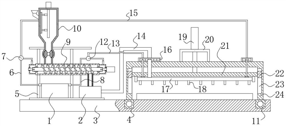
[0026] see figure 1 , the present embodiment, a thermoplastic powder melting device, comprising a feed tank 10, a hot melt cylinder 9, a steam furnace 1, an extruder 2, a frame 5, a bottom plate 3 and a spray pipe 17, the frame 5 is fixedly installed on the bottom plate 3, the feed tank 10, the hot melt cylinder 9, the steam furnace 1 and the extruder 2 are all set on the frame 5, and the bottom plate 3 is provided with a gantry sliding along the front and rear 24. The spray pipe 17 is longitudinally slidably arranged on the gantry 24, and the gantry 24 is provided with a cylinder 19 for driving the longitudinal slide of the spray pipe 17. Drive the gantry 24 to slide back and forth through the driving device, and then drive the spra...


PUM


Abstract

The invention provides a thermoplastic plastic powder spray fusing device. The device comprises a feeding tank, a hot melting drum, a steam furnace, an extruding machine, a rack, a bottom plate and amaterial spraying pipe; the rack is fixedly installed on the bottom plate; the feeding tank, the hot melting drum, the steam furnace and the extruding machine are arranged on the rack; a portal frameis arranged on the bottom plate in a back-and-forth sliding mode; the material spraying pipe is arranged on the portal frame in a vertically sliding mode; an air cylinder is arranged on the portal frame and is used for driving the material spraying pipe to slide vertically; a feeding hopper is arranged on the side wall of the feeding tank; a discharging pipe at the bottom of the feeding tank is connected with a feeding port of the hot melting drum; a quantified discharging device is arranged on the discharging pipe at the bottom of the feeding drum; a shaft sleeve is rotatably installed insidethe hot melting drum in a coaxial sealing mode; a discharging end of the hot melting drum is connected with the extruding machine; hollow spiral plates are distributed on the shaft sleeve along the axial direction; sealing shades are installed at two ends of the hot melting drum in a sealing mode; and the end parts of the shaft sleeve extend into the sealing shades.

Description

technical field [0001] The invention relates to a melting device, in particular to a melting device for thermoplastic powder. Background technique [0002] Plastic has become the most frequently used material in people's daily life. With the advancement of technology, plastics that have been continuously improved are widely used in the manufacture of building parts, food containers, living utensils, electrical housings, and aerospace vehicles. In recent years, , Plastics have begun to be used in the manufacture of functional composite materials and other occasions. In the processing and manufacturing of thermoplastic powder, due to the small size of the plastic powder particles, it is often impossible to pave according to the purpose of use in actual use. During the preparation, the plastic powder will be deposited at the bottom of the composite raw material mixture due to gravity, resulting in material distribution. Inhomogeneity may affect the mechanical properties and ap...

Claims


Application Information

Patent Timeline
Patent Type & Authority Applications(China)
IPC IPC(8): B05B13/02B05B9/00B05B15/68
CPCB05B9/002B05B13/0278B05B15/68
Inventor 白凤林
Owner 蒙城县虹升塑粉有限公司
Why Eureka
Try Eureka