Continuous feed and cutoff device of fibers

A cutting device and continuous technology, applied in the direction of transportation and packaging, metal processing, conveying filamentous materials, etc., can solve the problems of unsatisfactory composite materials, high production cost, low production efficiency, etc., achieve simple and convenient operation, and improve mechanization The effect of the degree of pipeline

Inactive Publication Date: 2015-10-07
HUANGHE S & T COLLEGE
View PDF14 Cites 7 Cited by
  • Summary
  • Abstract
  • Description
  • Claims
  • Application Information

AI Technical Summary

Problems solved by technology

Most of the current fiber feeding and cutting equipment cannot meet the requirements of online injection molding of composite materials, and the production efficiency is low and the production cost is high

Method used


Image

  • Continuous feed and cutoff device of fibers
  • Continuous feed and cutoff device of fibers
  • Continuous feed and cutoff device of fibers

Examples


Embodiment 1

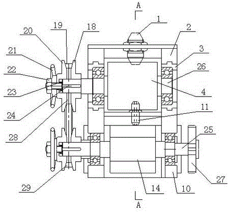
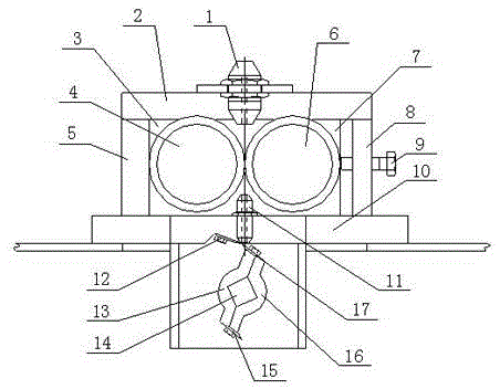
[0021] Such as figure 1 , figure 2 As shown, the present invention provides a continuous fiber feeding and cutting device, including a base 10, a first rotating shaft 25, and a second rotating shaft 26, wherein the second rotating shaft 26 is located above the first rotating shaft 25 and is connected to the first rotating shaft. The shafts 25 are parallel, and the first rotating shaft 25 and the second rotating shaft 26 are rotationally connected with the base 10 , wherein the rotation of the first rotating shaft 25 and the second rotating shaft 26 can be realized by setting a bearing on the base 10 . The left end of the second rotating shaft 26 is provided with a second infinitely variable transmission member 29, the right end of the first rotating shaft 25 is provided with a transmission wheel 27, and the left end of the first rotating shaft 25 is provided with a first continuously variable transmission member 28. A rotary cutter shaft 14 is provided, and the first continu...

Embodiment 2

[0031] Its general structure is the same or similar to that of the pipe sealer provided in Embodiment 1, so it will not be repeated here, and only the differences will be described below.

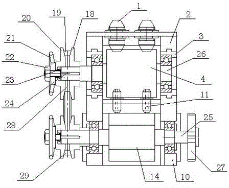
[0032] Such as image 3 A pair of wire inlet nozzles 1 and wire outlet nozzles 11 are provided in the first embodiment shown above, but in order to increase the feed rate, two pairs of wire inlet nozzles 1 and wire outlet nozzles 11 are provided in the second embodiment, so that the fiber feed mode is changed from Single-line feeding is changed to double-line feeding to meet the needs of production.

[0033] In the first and second embodiments above, there are one pair and two pairs of wire inlet nozzles 1 and wire outlet nozzles 11. In the actual production process, the number of wire inlet nozzles 1 and wire outlet nozzles 11 can be increased or decreased according to the needs of product production.


PUM


Abstract

The invention relates to a continuous feed and cutoff device of fibers. The continuous feed and cutoff device mainly comprises a roll type continuous feed mechanism, a rotary cutoff mechanism and a mechanical continuously variable transmission mechanism. When the device runs, fiber lines pass through a feeding nozzle, penetrate through a gap between a fixed roll and an adjusting roll and enter the rotary cutoff mechanism. A transmission wheel is driven to rotate through drive rotation of external power, and rotary shafts are driven by the transmission wheel to achieve continuous feed and rotary cutoff on the fiber lines. Meanwhile, the reference diameter of transmission belts between left transmission wheel sheets and right transmission wheel sheets is changed by loosening locking nuts and adjusting hand wheels, continuously variable transmission is achieved, and then the feed speed and cutoff length of the fibers are adjusted. According to the device, a single fiber line can be introduced, multiple fiber lines can be introduced, continuous and even feed and cutoff are achieved, work efficiency is greatly improved, the adjustment range of different fiber lengths and different adding quantities is wide through the continuously variable transmission mechanism, and needs of different products are met.

Description

technical field [0001] The patent of the present invention relates to the field of plastic machinery, in particular to a continuous fiber feeding and cutting device. Background technique [0002] Fiber refers to a substance consisting of continuous or discontinuous filaments. Fibers are widely used, and can be woven into thin threads, thread ends and hemp ropes, and can also be woven into fiber layers when making paper or felt; they are also commonly used to make other materials, and to form composite materials with other materials. Fibers are used in the textile industry, military , environmental protection, medicine, construction, biotechnology, plastics and many other industries are widely used. Especially in the plastic manufacturing process, the fiber filling can effectively improve the strength and stiffness of the plastic. Among them, in the online injection molding process of reinforced polymer composite materials such as short fibers (glass fibers or carbon fibers...

Claims


Application Information

Patent Timeline
Patent Type & Authority Applications(China)
IPC IPC(8): B65H51/08B65H57/06B26D1/25
Inventor 张燕燕郭晓君朱煜钰陈会鸽常静翟宝玉董召阳
Owner HUANGHE S & T COLLEGE
Why Eureka
Try Eureka