

Optical head device and optical information device
An optical head device and information recording technology, which is applied in the direction of optical recording head, beam guiding device, information storage, etc., can solve the problems of increasing the number of components, difficulty in realizing device miniaturization, and difficulty in reducing costs
- Summary
- Abstract
- Description
- Claims
- Application Information
AI Technical Summary
Problems solved by technology
Method used
Image

Examples
no. 1 example
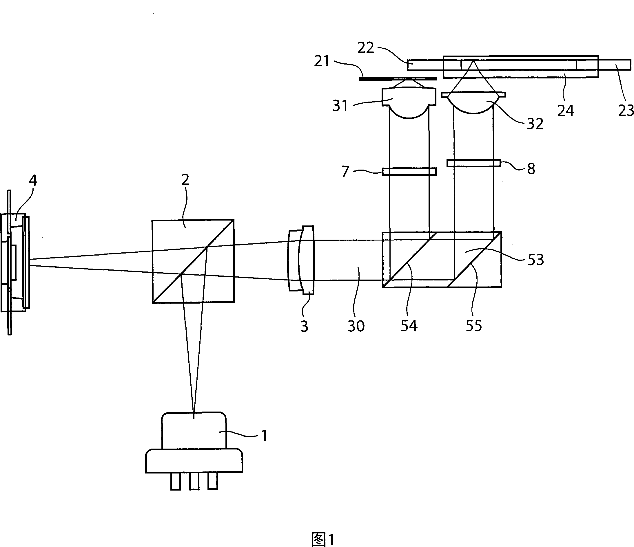
[0018] First, an optical head device according to a first embodiment of the present invention will be described with reference to FIG. 1 . FIG. 1 is a schematic diagram showing the configuration of an optical head device according to a first embodiment of the present invention.
[0019] The optical head device shown in Fig. 1 comprises, light source 1, polarizing beam splitter (polarization beam splitter) 2, collimator lens (collimator lens) 3, photodetector 4, wavelength plate (wave plate) 7,8, objective lens 31 , 32 and prism 53 . In addition, the optical disc 21 is a BD with a protective layer thickness of about 0.1 mm, the optical disc 22 is an HD-DVD with a protective layer thickness of about 0.6 mm, the optical disc 23 is a DVD with a protective layer thickness of about 0.6 mm, and the optical disc 24 is a protective layer with a thickness of about 0.6 mm. It is a 1.2 mm CD, and each of the optical discs 21 to 24 is an information recording medium having a track on whic...
no. 2 example
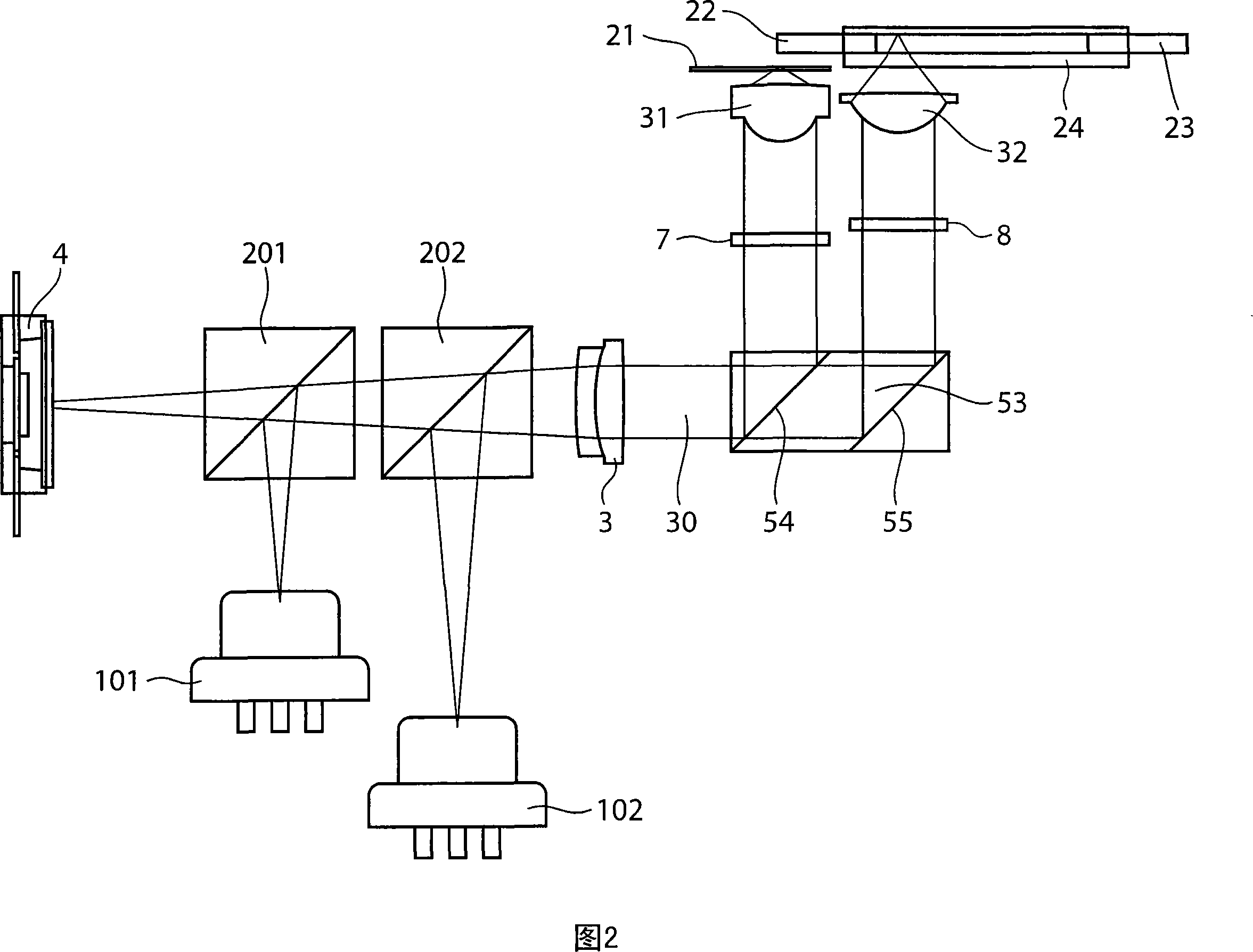
[0036] Hereinafter, an optical head device according to a second embodiment of the present invention will be described with reference to FIG. 2 . FIG. 2 is a schematic diagram showing the configuration of an optical head device according to a second embodiment of the present invention. The difference between the optical head device shown in FIG. 2 and the optical head device shown in FIG. 1 is that two light sources 101, 102 and two polarized beam splitters 201, 202 are used instead of one light source 1 and one polarized beam splitter. The beam mirror 2 is the same as the optical head device shown in FIG. 1 in other points, so the same symbols are assigned to the same parts, and detailed description thereof will be omitted.
[0037] The light source 101 emits laser light with a wavelength of 405 nm, and the polarized beam splitter 201 reflects the laser light from the light source 101 , and guides the laser light into the collimator lens 3 through the polarized beam splitter ...
no. 3 example
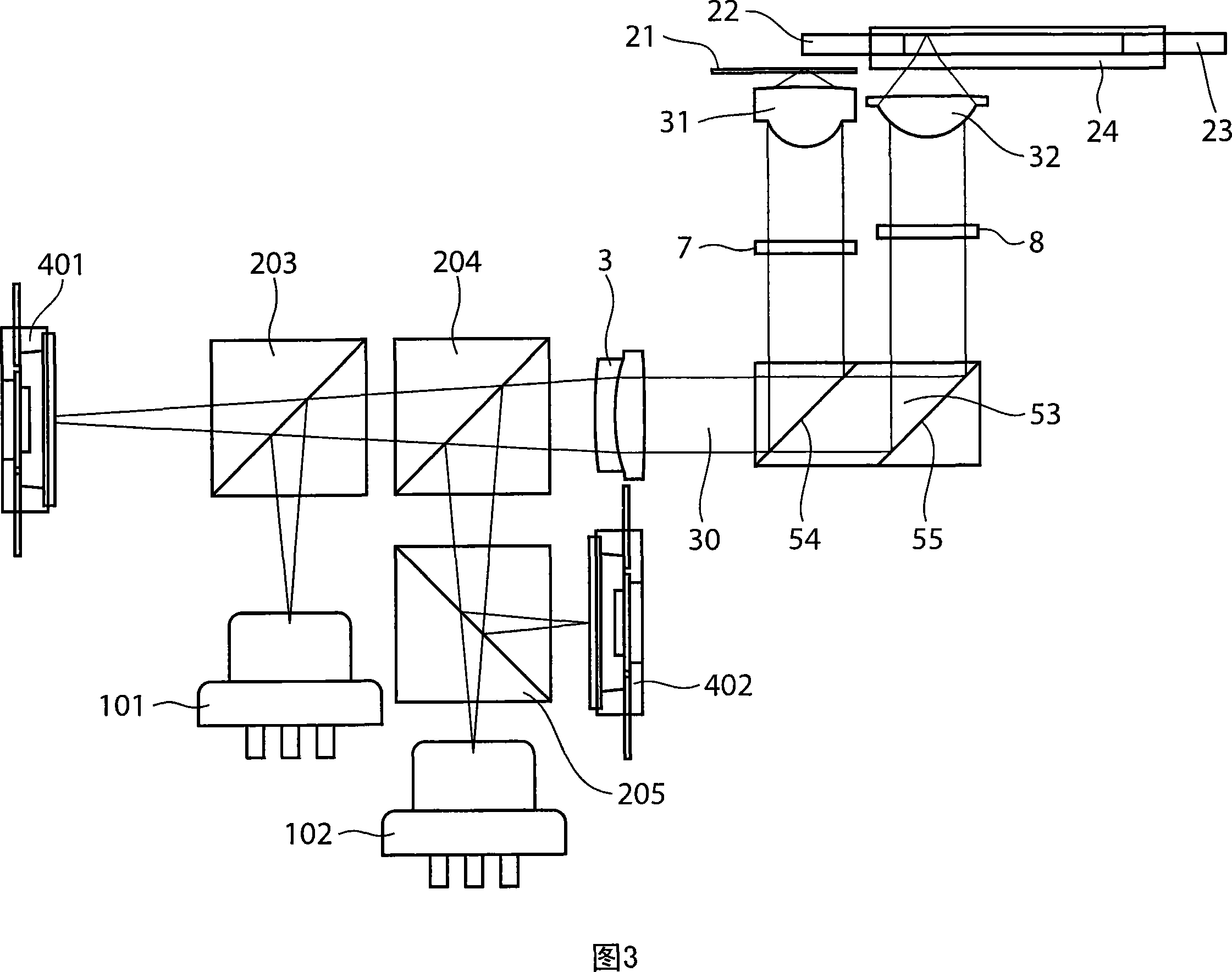
[0041] Hereinafter, an optical head device according to a third embodiment of the present invention will be described with reference to FIG. 3 . 3 is a schematic diagram showing the configuration of an optical head device according to a third embodiment of the present invention. The difference between the optical head device shown in Figure 3 and the optical head device shown in Figure 2 is that three polarized beam splitters 203, 204, 205 and two photodetectors 401, 402 are used to replace two polarized light beams The beam splitters 201, 202 and one photodetector 4 are the same as the optical head device shown in FIG. 2 in other points, so the same reference numerals are assigned to the same parts, and detailed description thereof will be omitted.
[0042] The laser beam with a wavelength of 405 nm from the light source 101 is reflected by the polarizing beam splitter 203 and guided into the collimator lens 3 by the polarizing beam splitter 204 . The action between the coll...
PUM
| Property | Measurement | Unit |
|---|---|---|
| wavelength | aaaaa | aaaaa |
| thickness | aaaaa | aaaaa |
Abstract
Description
Claims
Application Information